This LDR circuit diagram shows how you can make a light detector. An LDR or “Light Dependent Resistor” is a resistor where the resistance decreases with the strength of the light.
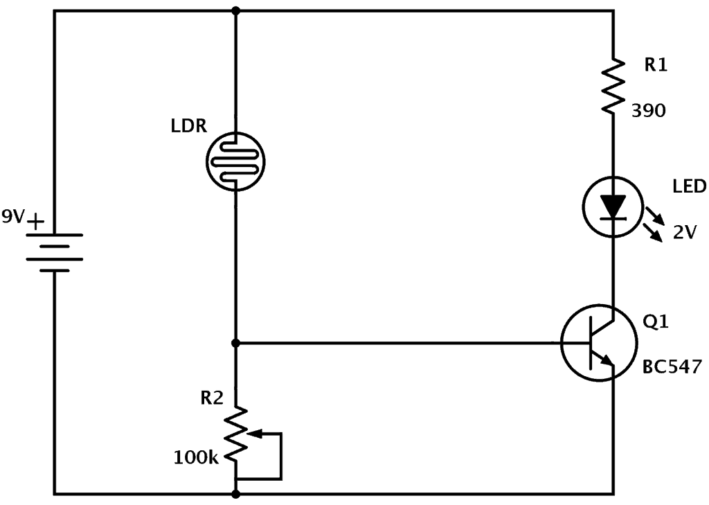
Here is the schematic for the circuit:
Light Dependent Resistors
Light Dependent Resistors (LDR) are also called photoresistors. They are made of high resistance semiconductor material. When light hits the device, the photons give electrons energy. This makes them jump into the conductive band and thereby conduct electricity.
Check out Wikipedia for the physics stuff ;)
How The LDR Circuit Diagram Works
The LDR circuit diagram works like this:
When it’s dark, the LDR has high resistance. This makes the voltage at the base of the transistor too low to turn the transistor ON.
Therefore, no current will go from the collector to the emitter of the transistor. All the current will instead pass through the LDR and the potentiometer.

Build Something Useful This Evening
This gadget lets you use any IR remote-control to control your lamp, garden lights, heater oven, garage door, or anything else.
When it’s light, the LDR has low resistance. This makes the voltage at the base of the transistor higher. High enough to turn the transistor ON.
Because the transistor is turned on, current flows through the transistor. It flows from the positive battery terminal, through R1, the LED, and the transistor down to the negative battery terminal.
This makes the LED light up.
The Components Used In The Light Detector Circuit
The resistor R1 controls the amount of current going through the LED. It’s simple to calculate. I have written an article on how to calculate the resistor value for an LED.
If you are using an LED with 2V voltage drop, you will have a 7V voltage drop over the resistor when the transistor is ON. By using Ohm’s law we can find the current:

And 18 mA is usually a good current value for common LEDs.
What if you want to power the circuit with something other than a 9V battery? Then you need to change the resistor value to get the right amount of current flowing through the LED.
The variable resistor R2 is used to change the trigger point for the LED. That is, how much light that is needed for the LED to turn ON and OFF.
You can probably get away with a 10k potentiometer. It depends on the resistance of your LDR. But with a 100k potentiometer you will have room for a wider range of LDR values.
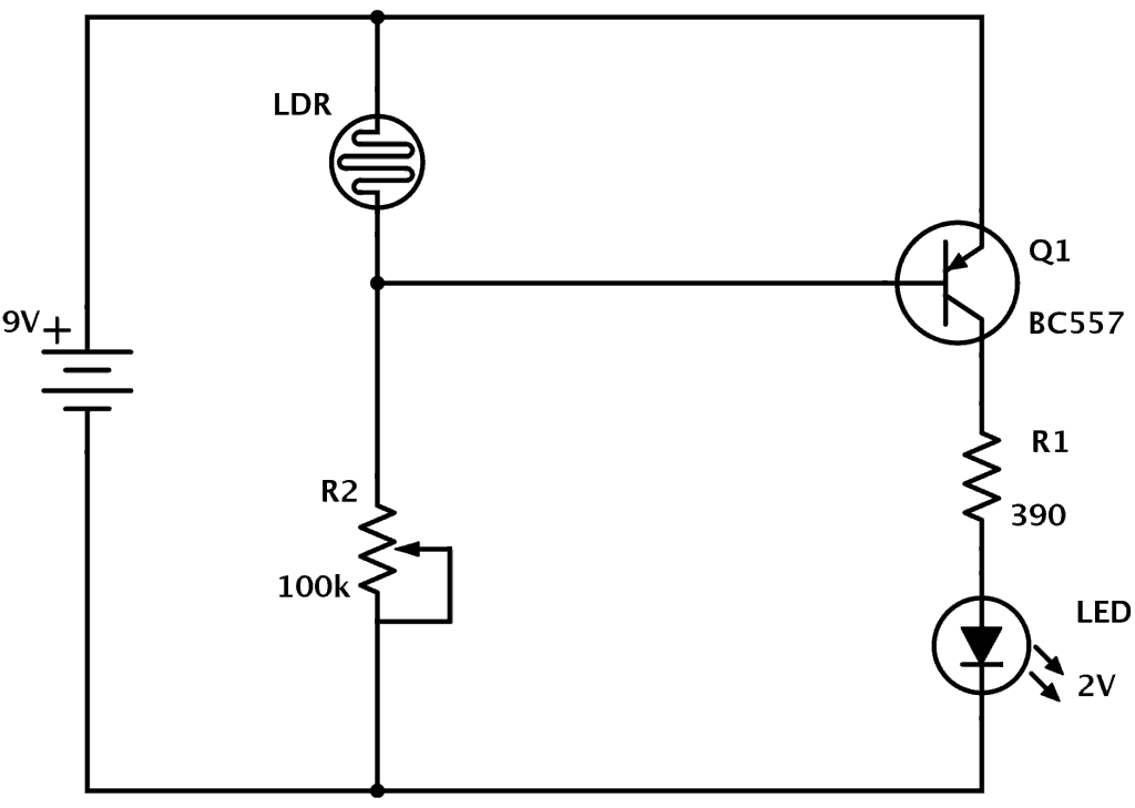
Making The LED Turn ON When it’s Dark
You can also make the LED turn ON when it is dark instead of when it is light. To do this, replace the NPN transistor with a PNP transistor like this:
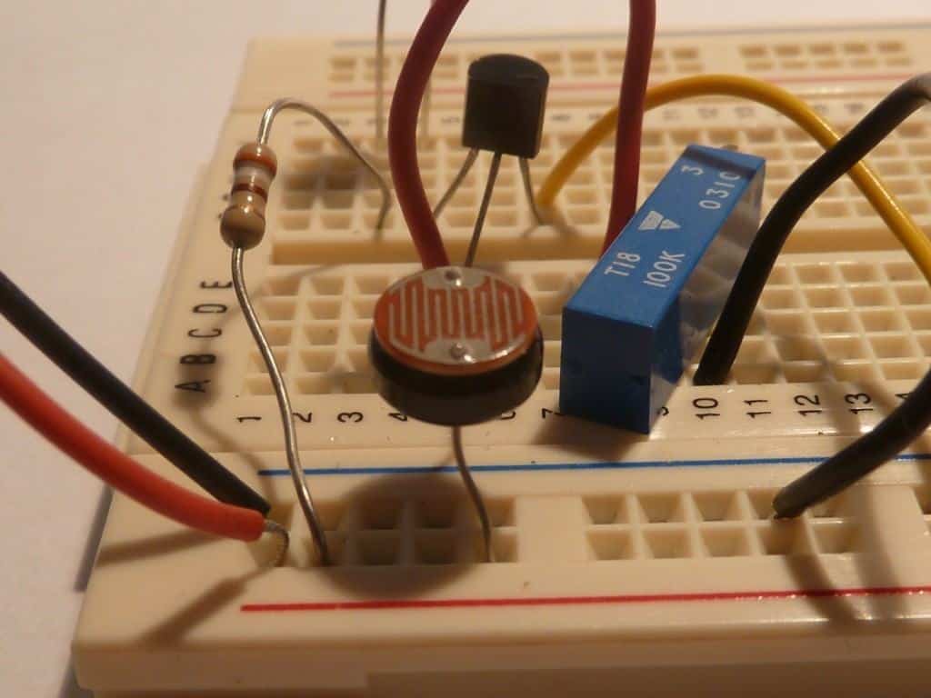
Build It Yourself
Now it’s time for you to build this circuit. It’s very important to build stuff, not just read about it. So get yourself the components you need and build it!
Get the required components from an online electronics shop.
Post your comments or questions below =)
More Circuits & Projects Tutorials
Build Something Useful This Evening
This gadget lets you use any IR remote-control to control your lamp, garden lights, heater oven, garage door, or anything else.
