fbpx

How To Build An Automatic Night Light Circuit

In this tutorial, you’ll learn how to build an automatic night light circuit that turns on when it gets dark. It’s a simple circuit that you can build on a breadboard.

This circuit shows you how to do it with an LED. But you can use the same principle to turn on bigger and brighter lights too.

Find the breadboard diagram and parts list below the video.

The Components You’ll Need

Night light circuit diagram
  • 9V Battery
  • Breadboard
  • Photoresistor (around 5kΩ in light, 200kΩ or more in dark)
  • Transistor BC547
  • Resistor 100 kΩ
  • Resistor 470 Ω
  • Light-Emitting Diode (LED)

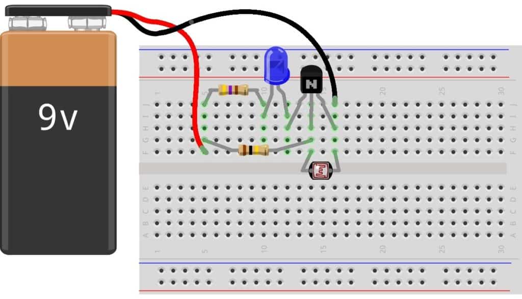
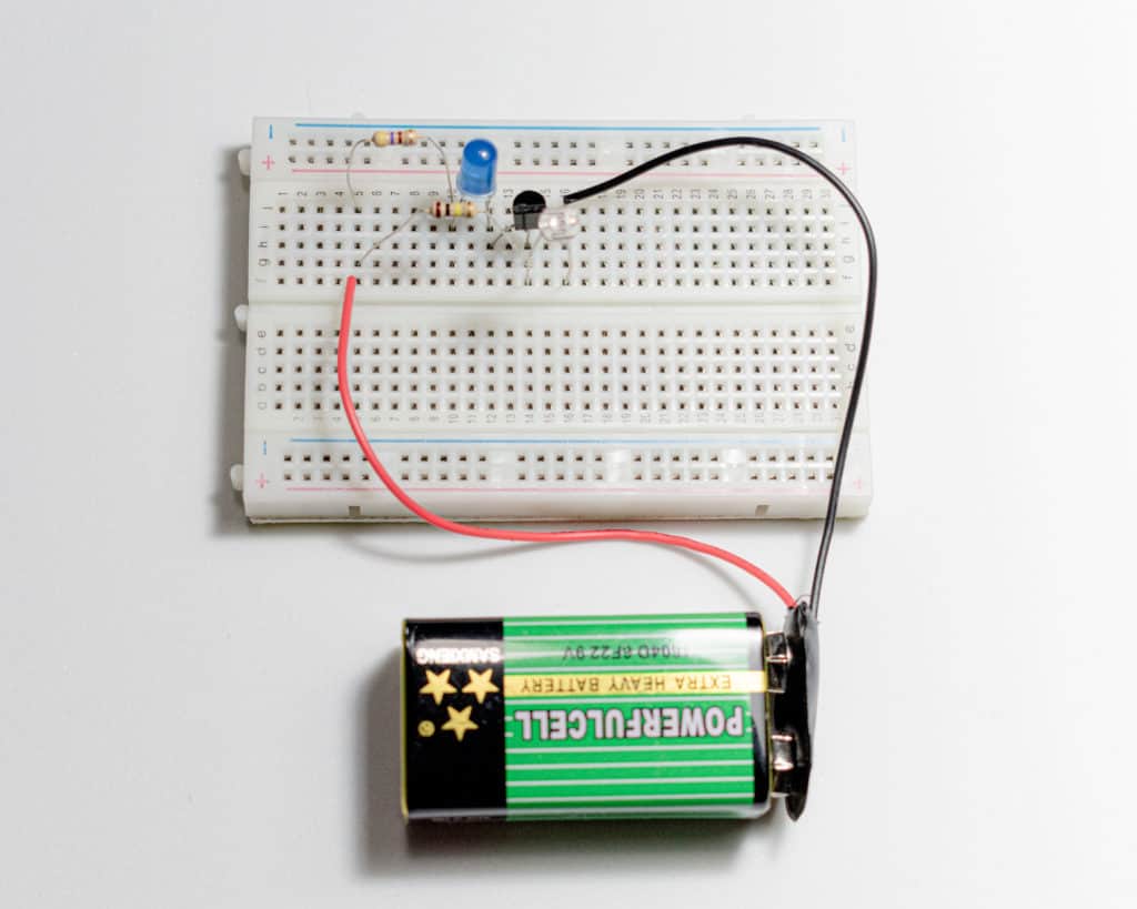
There are many ways to connect this circuit. I recommend using a breadboard since it’s quick and you can easily reuse components.

Below you can see how I connected this circuit on a breadboard:

Night light circuit on breadboard

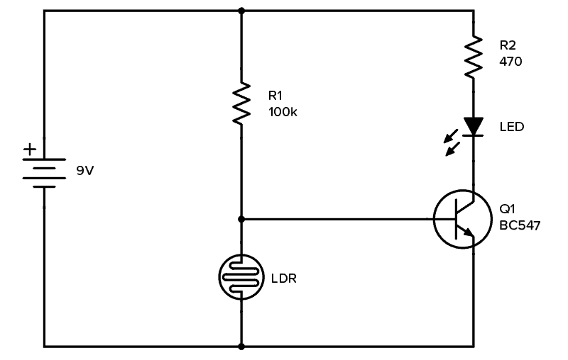
How The Night Light Circuit Works

The photoresistor and the 100 kΩ resistor make up a voltage divider.

When there is a lot of light, the photoresistor will have low resistance, which means the voltage divider gives a low output voltage. So the transistor is off and cuts off the current to the LED. Which means no light.

When it’s dark, the photoresistor will have high resistance. That means the voltage divider gives a high output voltage which turns on the transistor. That means the LED is also on and will light up.

The finished night light circuit

What Are the Voltages out From the Voltage Divider?

When it’s light and the photoresistor value is low, the output from the voltage divider is around 0.5V, which is not enough to turn on the transistor.

When it’s dark and the photoresistor value is high, the output from an unconnected voltage divider would be around 4.5V.

But since the output of the voltage divider is connected on the base of the transistor, the voltage will be limited by the forward voltage of the base-emitter connection (around 0.7V).

Questions?

Did you build the night light circuit? Do you have any questions about how it works or how to build it? Let me know in the comment section below.

More Circuits & Projects Tutorials

46 thoughts on “How To Build An Automatic Night Light Circuit”

  1. Hi,
    how can you change the threshold? I mean, there’s an amount of light when the photoresistor changes from low to high value. I guess there are different photoresistor models, but having just one photoresistor, can you adjust the circuit in a way that the led will turn on when there’s more or less light. I guess the only variable in the circuit is the other resistance, but how can higher or lower resistance affect the circuit?
    Thanks.

    Reply
    • Hi, just replace R1 with a variable resistor (potentiometer) and you can adjust the threshold for when it turns on and off.

      Reply
      • Thanks. I was more hoping the answer to be something along: if the value of the resistance is lower, the led will turn on when it receives more light or the other way around.

        Reply
        • R1 and LDR form a voltage divider.
          LDR typically has a resistance of 20k in darkness and near 0 in bright light and somewhere in between otherwise.

          the voltage at the base, Vb is triggered at Vt (3-5 volts). Higher =ON; lower= OFF
          if R1=Rldr around 20k the voltage is half of vcc.
          The higher R1 is the lower Rldr appears and Vb is closer to Vcc.
          Lowering R1 brings Vb closer to ground.
          A direct short to ground and it would take a super gamma burst to turn the circuit on.

          Reply
          • Also, switch places of R1 and Rlde, and the opposite effect is achieved – a light detector rather than a darkness detector.

    • I used what I had on hand – probably 0.25W. The 470 resistor has the biggest power requirement of around 0.1W – so 0.25W is sufficient for all the resistors in this circuit.

      Reply
      • I used other circuit and zero pcb although only slight difference in components that I used 1k ohm resistor series with transistor and 330 ohm resistor with LDR. other bc547 transistor with 1N4007 diode this 3 connection in parallel and last a 6v relay connect across diod and transistor and than bulb connected with AC supply. Could you please please tell me how voltage divider works in this circuit and briefly about it’s functionality. Please help me

        Reply
  2. Hello, i used a 2N2222A transistor on my project & Led strip(i had 3 Leds on that strip).
    I was curious if it worked if i flip all around & it did the same job, why?

    2N222A pins should be 123(as E B C) if you look the transistor from the flat side, so it would be from left to right.

    How i connected everything:
    LDR connects to Base(Pin2) and Emitter(pin1)
    100K resistor connects to Base(Pin2) & positive side of the battery
    Red Led/LED strip connects from Collector(Pin3) to resistor & that resistor connects to a positive side of the battery.
    Negative battery connects to a Emitter(Pin1)

    I think i might have missed something in the Datasheet that explanes how it differs from BC547.

    I used his page for the datasheet:
    https://components101.com/2n2222a-pinout-equivalent-datasheet

    I would appreciate for the clarification.

    Reply
  3. Hi. I try the circuit and it work perfectly but my problem is that the output volt is not enough to bighting the led. out can i use the circuit to achive a brighter light or to get am output of 6-9v then the 2.5v the circuit is bring out. thanks

    Reply
  4. Hi !
    you said in the dark the voltage on the LDR will be about 4.5V, in the same time the transistor just needs a 0.7V to conduct, won’t this make a lot more current goes through the LED and burn it?

    Reply
  5. I have constructed the experiment according to the circuit diagram given ,using all of components given above and my LED is ON once once I connect the battery but the problem is that LED is always ON i.e it is ON during darkness and also when light is present .
    Could it be because there is an error with the photoresistor ?

    Reply
  6. Very nice. Thank you. I used sort of random transistor I had from a starter kit. Thank fully, it worked. I really like these smaller setups w/o using a micro controller (although those are fun too)

    Reply
  7. Instead of just assuming a 9V source and stating “work out the values for other voltages” why not include the calculation in the explanation. Then you can learn from the example without having to find the relevant information to calculate different values.

    I cite this because the pp3 battery, whilst still the ubiquitous power source, is fast being replaced by lithium cells – which are rechargeable, cheap, free or can be found littering the streets ( I have a box of over 100 vape cells from 200mAh to 1000mAh – and yes it requires a slightly higher level of understanding to use them, but 18650 and suitable chargers are as cheap as the chips that control them).

    This is designed to be a roots up course but it would be more effective if you stated the method of achieving the given values in each example, rather than just offering a set of components with set values.
    It would speed up the learning process and save having to keep referring back to other information.

    Reply
  8. Hi, I constructed the circuit according to the schematic diagram, but for some reason the LED is on when light is present but off when there is no light. The only difference between our circuits is that I’m using a 470 ohm 5 band resistor instead of 4 band. Any idea on what could be happening?

    Reply
    • Hi, given that you’ve connected everything correctly, the only thing that comes to mind to explain that behaviour is that you’re using a different transistor than the bc547. It needs to be an NPN transistor, not PNP.

      Reply
  9. Thanks for posting this project. It worked fantastically for me.. I am only learning electronics and to have the project explained so clearly was a great encouragement. I will certainly try more of your projects.

    Reply
  10. what if im only provided with 9 V d.c. power supply, light bulb (2.5 V, 0.3 A), light bulb (4.8 V, 0.3 A), 3 L.E.D. and 2 resistors (180 Ω) and 1 resistor (390 Ω). sorry for all the trouble but help will be much appreciated :)

    Reply
  11. Hi, I love your set, it’s a fantastic resource for a total beginner like me!

    One thing has me confused though. I built the circuit as you have shown, but used a P2N2222 transistor as that was all I had available.

    The circuit works – but it works with the transistor inserted either way round, ie with either E or C connected to the LDR.

    Any idea why would that be?

    Thanks for your help,
    Bruce

    Reply

Leave a Comment