When you connect capacitors in parallel, you connect them alongside each other. And the result becomes a capacitance with a higher value. In this guide, you’ll learn why it works like that, how to calculate the resulting capacitance, and some examples of this in practice. As you’ll soon see, this is actually very simple.
How to Calculate the Value of Capacitors in Parallel
Calculating capacitors in parallel is very easy. You just add the values from each capacitor. If you want to be fancy about it, here’s the formula:

So if you place a 470 nF capacitor and a 330 nF capacitor in parallel, you’ll end up with 800 nF. You add as many capacitors as you want.
Example
Imagine that you connect three 1000 µF caps in parallel. What’s the total capacitance of these three capacitors?
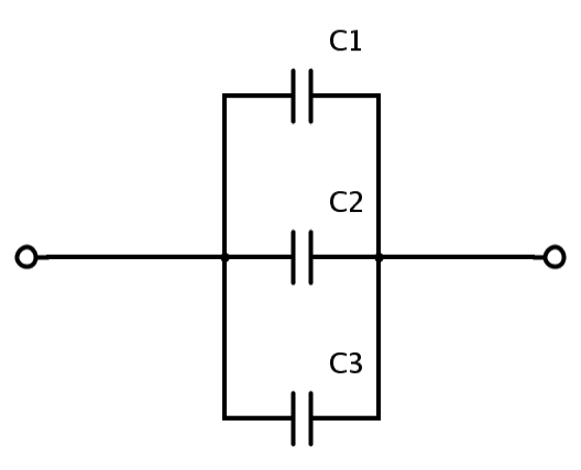
1000 µF + 1000 µF + 1000 µF is 3000 µF. So the total capacitance of the three capacitors becomes 3000 µF.
This can be useful for getting a specific capacitor value that you don’t currently have in your component selection. Combine this technique with adding capacitors in series, and you can create a lot of different values out of just a few.
Why Does it Work Like This?
The formula for calculating capacitors in parallel makes sense when you think about how capacitors work: A capacitor is basically just two metallic plates, placed close to each other, with an insulating material in between.

Get Our Basic Electronic Components Guide
Learn how the basic electronic components work so that circuit diagrams will start making sense to you.
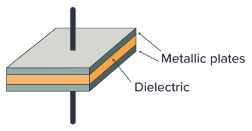
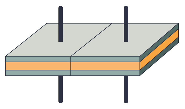
The larger the plates, the higher the capacitance. So when you place two (or more) capacitors in parallel, it’s more or less the same as using bigger plates.
Voltage Across Capacitors in Parallel
The voltage across capacitors connected in parallel is the same for each capacitor. If you know that there is 5V across one capacitor, it means that all the other capacitors that are connected in parallel with this also have 5V across.
This isn’t specific to capacitors. Any type of component in parallel will have the same voltage for all the components. If this sounds like a mystery to you, I recommend reading up on the basics of voltage and current.
Why Connect Capacitors in Parallel?
The most common reason for connecting capacitors in parallel among hobbyists is simply that you don’t have the exact capacitor value that you need.
Let’s say you want to build a blinking light circuit that blinks at some specific rate. You’ve calculated that you need a capacitor of 147 µF. In your component box, you don’t have this value, but you have 100 µF and 47 µF.
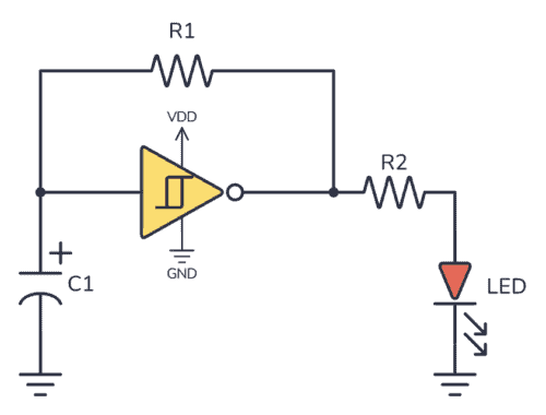
Well, just replace C1 in the circuit above with a 100 µF and a 47 µF capacitor in parallel, and you end up with a total capacitance of 147 µF.
Another typical place where you’ll see capacitors connected in parallel is with microcontroller circuits. Microcontroller chips often have several power pins. And it’s common to place a capacitor from each positive power pin to ground.
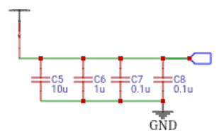
In this case, the point isn’t to get a new capacitor value, but instead to show you how many capacitors you’ll need for the circuit. Although they are connected in parallel, they’ll be distributed across the board.
Summary
To get the total value of capacitors connected in parallel, just add up the value of each. Ex five capacitors of 1 µF become 5 µF. And three capacitors of 100 nF become 300 nF.
For simple circuits, you usually only place them in parallel if you need a specific value that you don’t have available.
Let me know your questions or comments below!
More Capacitors Tutorials
Get Our Basic Electronic Components Guide
Learn how the basic electronic components work so that circuit diagrams will start making sense to you.