In this guide you are going to learn what a photodiode is, how it works, and more importantly, how you can use it in your own circuits. We’ll go through the basics, then build a fully working fire sensor circuit!

Did you know that there are two different ways to use photodiodes? Both of them are straightforward once you’ve learned them, but one is more common than the other.
Ok, let’s jump in!
What Is a Photodiode?
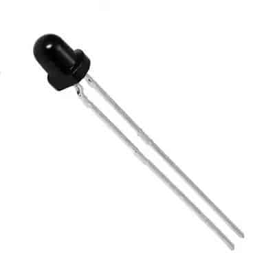
A photodiode is a diode that senses light. It has two legs and comes in various shapes and packaging. When light hits a photodiode, current flows through it in one of two ways: either a small current is created from the light, or the light allows a larger current to flow through.
The photodiode symbol looks like the symbol for the light-emitting diode, except that its arrows point inward.

How To Use a Photodiode
When you operate a photodiode without any bias voltage, shining light on it generates a small voltage across its terminals.

If you connect a resistor across it, a very small current flows through the resistor. This is called photovoltaic mode and works best in low-frequency conditions (i.e. when the light does not turn on and off really fast).

On the other hand, when it is reverse biased, i.e. the anode is connected to the negative voltage and the cathode to the positive voltage, it is in photoconductive mode. In this mode, it works more like a switch. Light on the photodiode “closes the switch” and current flows through the photodiode:

Get Our Basic Electronic Components Guide
Learn how the basic electronic components work so that circuit diagrams will start making sense to you.

In this mode, it can switch on and off much faster. Photodiodes are usually used in this mode.
That said, the circuit above isn’t really a practical one since the current through the diode will be tiny (typically a few microamperes).
How Does a Photodiode Work?
Internally, a photodiode has a p-n junction, which is formed when a p-type semiconductor material is fused with an n-type semiconductor material. A p-type semiconductor material has holes as positive mobile charge carriers, while an n-type semiconductor material has electrons as negative mobile charge carriers.
Since the p-n junction has oppositely charged mobile carriers, they neutralize each other and form a depletion region at the juncture. It is called a depletion region because it is devoid of any mobile charge carriers. The part of the p-type material in the p-n junction is devoid of holes, so it becomes negatively charged. Similarly, the part of the n-type semiconductor in the p-n junction becomes positively charged.
When photons – or light – of sufficient energy fall on the p-n junction of the photodiode, they break and ionize the covalent bonds of the immobile atoms. This generates new electron-hole pairs. This phenomenon is called the photoelectric effect. The generated electrons are swept toward the n-type material (because the depletion region of the n-type material is positively charged). The holes are swept towards the p-type material (because the depletion region of the p-type material is negatively charged). This flow of charge leads to photocurrent or simply current.
In other words, a photodiode senses light and produces current as output. A photodiode is also called a photo sensor, photodetector, or light detector.
Your First Photodiode Circuit – a Fire Sensor
You can build your first photodiode circuit using just a few components on a breadboard. This circuit will sense fire and raise an alarm. The component list is:
- IR-range photodiode (any electronics component hardware shop will have one)
- BC547 transistor (or other general-purpose NPN transistor)
- Buzzer (Active)
- Light-Emitting Diode (LED)
- 470 Ω resistor (R1)
- 9V battery
- Breadboard

Connect this circuit on a breadboard as shown in the image below:

How This Circuit Works
When IR light (from a fire) falls on the reverse-biased photodiode, a current flows through it. This triggers the base terminal of the transistor. The BC547, which was previously off, switches on and starts conducting current between its collector and emitter terminals. This current also flows through the buzzer, producing an alarm, and triggering the LED to glow.
The LED-resistor pair is there to add a light indication in addition to the sound from the buzzer. If you want to keep the circuit simple, feel free to skip it.
Typical Photodiode Circuits
Photodiodes can be used in a variety of ways, but the most commonly used circuits are the two below that use operational amplifiers (op-amps).
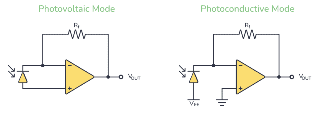
In the photovoltaic circuit, you connect the photodiode in forward-biased mode. The anode of the photodiode is connected to the non-inverting terminal and the cathode to the inverting terminal of the op-amp. When light falls on the photodiode, it generates a small voltage and current. The op-amp amplifies this and outputs a voltage. The size of the voltage depends on the value of the feedback resistor RF.
In the photoconductive circuit, you connect the photodiode in reverse-biased mode. In the circuit diagram above, VEE is a negative voltage. When light hits the photodiode, a small current passes through it, and an amplified voltage is available at the output.
In both cases, the op-amp is working as a trans-resistance amplifier or a current-to-voltage amplifier.
Check out this Arduino remote control project that uses a photodiode in photoconductive mode, packaged as a compact IR receiver.
Types of Photodiodes
There are four main types of photodiodes:
- PN photodiode: a simple p-n junction photodiode used in reverse-biased mode.
- PIN photodiode: a p-n junction photodiode with an intrinsic semiconductor layer between the p- and n-type material at the juncture. It is used when a greater surface area for light exposure is needed.
- Avalanche photodiode: a p-n junction photodiode that can be used in deep reverse-biased conditions. It has a higher photovoltaic current as a larger number of electron-hole pairs get generated in the p-n junction.
- Schottky photodiode: this is made of multiple Schottky diodes and operates at a higher speed and at larger wavelengths.
You can find photodiodes in most shops that sell electronic components. Check out our list of online electronic component shops.
What’s the Difference Between a Photodiode and a Phototransistor?
The photodiode is very similar to the phototransistor. They are both light-triggered devices that are connected in the same way in a circuit.
The difference is that a phototransistor is a transistor with a photodiode connected to its base. When light hits the photodiode, current flows through the base, and the transistor turns on so that current can flow through it.
In most cases, a phototransistor is easier to work with.
Check out our beginner’s tutorial on the phototransistor.
More Diodes Tutorials
Get Our Basic Electronic Components Guide
Learn how the basic electronic components work so that circuit diagrams will start making sense to you.