Reading schematics is just a matter of recognizing the symbols and see how they connect.
A symbol usually represents a part. Except for the ground and VCC symbols which just means connection to supply power.
The lines between the symbols represents wires that connect the components. That’s all.
Check out the electronic symbols.
Component Names and Values
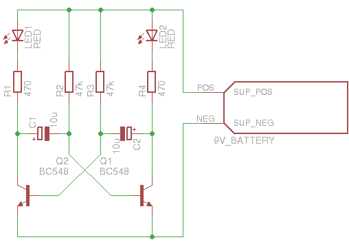
Often, the symbols have both a name and a value attached to it, such as R1, 100k. The name is there to name the components and the value shows what kind of value this part should have.
Electrical Connections Only
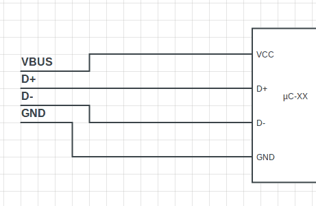
A schematic you find on the Internet sometimes includes only electronic components and no connectors. That is, instead of putting a symbol for a battery connector, you just see a line with a 9+ in the end of it. Or instead of a USB connector, you will see four lines with names such as VBUS, D+, D-, GND.

10 Simple Steps to Learn Electronics
Electronics is easy when you know what to focus on and what to ignore. Learn what "the basics" really is and how to learn it fast.
This is because schematics explain how components are electrically connected to make a specific function. Not to explain how to physically create the circuit. That is the job of the board layout.
Missing Pins
Sometimes, some of the pins of a component are missing from the schematic.
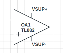
In the example below you can see an operational amplifier (op-amp). The symbol shows only three pins. But the op-amp has two more pins: VSUP+ and VSUP-. Why aren’t they showing up?
The reason for this is to make the drawing simpler.
Wire Names
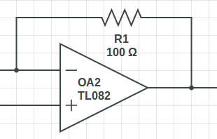
Sometimes you will see a wire stopping at a text such as “input” or “Vref”. That means the designer has named this wire. This means that all other wires with the same name are actually connected. And it also says something about its purpose.
For example, if you are reading schematics for an amplifier and you see a wire named “input”, what do you think its purpose is? It is probably where you connect your input to the amplifier ;)
Summary Of Reading Schematics
To read a schematic diagram, you need to know
- The electronic symbols
- That lines between components represent wires
Return from Reading Schematics to Electronic Schematics
More Schematic Diagram Tutorials
10 Simple Steps to Learn Electronics
Electronics is easy when you know what to focus on and what to ignore. Learn what "the basics" really is and how to learn it fast.

I wanted to see and touch ele-
tronics. This wish was for our
‘students. Yes, they do no see
and touch and you came on
the way. I AM in a small village
in India. an our technical is
working in two year’s gover
ment courses. One request: do
nat ask me money bu I shall
give you. my friend ship.
I can help you with your electronic classes and guide you how to train your students free of cost. I would like to help students from any village . contact me on [email protected] or shanakrvee@hot mail.com
I’ll be happy if you can help me out
Hey michael, I can also help your students. Message me regarding this issue on my email id – [email protected]
Thanks for letting me help in future.
Siddharth singh
Indian
Ovine , I am enjoying your building electronics circuits at the age of 55 years old . Can you please explain when working of a schematic drawing how to run the wiring on a breadboard . The drawing is clear but how is wired . Thank you
Hey Tony,
That’s great to hear.
Maybe this breadboard article will make it more clear: https://www.build-electronic-circuits.com/breadboard
Best,
Oyvind