When you start learning about electronics, you might see a circuit diagram drawn with realistic looking drawings of the different components.
But this method is not very effective.
To make them more effective, all electronic components have been assigned much simpler symbols. And wires are drawn as lines to show how to connect them.
It’s not always easy to understand a circuit diagram. But with practice and experience you will understand more and more.
What is a circuit diagram?
A circuit diagram, or a schematic diagram, is a technical drawing of how to connect electronic components to get a certain function.
Each electronic component has a symbol. After seeing a few circuit diagrams, you’ll quickly learn how to distinguish the different symbols.

Get Our Basic Electronic Components Guide
Learn how the basic electronic components work so that circuit diagrams will start making sense to you.

How do you read circuits diagrams?
Reading schematics is actually pretty easy.
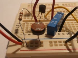
Each of the lines are wires. These show how the components are connected. If you want to build the circuit, you only need to get the components specified, then connect them as shown in the circuit diagram. This can be done either on a breadboard, a stripboard or you can design your own printed circuit board (PCB) if you like.
A circuit diagram should be specific enough so that anyone can make the circuit just by following it. You don’t actually need to understand it in order to build it.
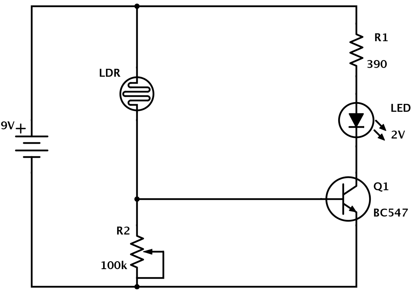
For example, look at the image above. I can buy a light-dependent resistor (LDR), a potentiometer, a resistor, an LED and a transistor. Then I can connect these on a breadboard by following the lines on the circuit diagram.
I would then have a circuit that has the specific function that this diagram was made for – without necessarily understanding why or how it works.
How do you understand how it works?
Understanding how a circuit diagram works can be a bit tricky. It comes from experience. You recognize the way some components are connected and identify known pieces of the schematic.
In the circuit above for example, I would see the LDR together with the potentiometer in the middle. I know from experience that two resistors setup like this makes a voltage divider. And I know that the voltage out from a voltage divider is a result of the values of those resistors.
I also know that the resistance of an LDR varies with the amount of light it receives. This means that the voltage out, i.e. the voltage on the base of the transistor, will vary with the amount of light detected by the LDR.
Then I look at the transistor. I know that the transistor can be turned on and off by applying a voltage at the base. So from this information, I would have an idea that this circuit will turn on and off the LED connected to the transistor, based on the amount of light the LDR receives.
BUT, if you are a beginner and you don’t know what an LDR is, what a transistor is or what a voltage divider is, then you won’t have the foundation to understand the circuit. So you need to start by learning those parts first before you can understand the circuit diagram.
To Sum It Up
Understanding comes with experience. You start by understanding small circuit chunks and later you’ll learn to identify those chunks in a bigger circuit diagram so that you can make sense of the big circuit diagram.
But you don’t have to understand a circuit diagram to be able to build it. That’s the cool thing! You can build things beyond your understanding and as you progress you will learn and understand more and more.
Return to from Circuit Diagram to Electronic Schematics
More Schematic Diagram Tutorials
Get Our Basic Electronic Components Guide
Learn how the basic electronic components work so that circuit diagrams will start making sense to you.
best
You say it can only be learned through experience. That’s true. But a beginner needs SOME kind of direction. Where do you get that direction? I’ve been looking all over the web for videos and text articles to no avail. There’s no way to ask questions and they all assume you already understand everything.
Absolutely. Over at Ohmify you can get help and you get courses that will teach you everything from scratch: https://ohmify.com/
I really learn something from this video.
Thanks, Oyvind.
I am really happy to hear that! =)
Oyvind
This video is very useful to me
thankyou
Great =)
Oyvind, is there a blog post about LDRs? I’m really curious as to how they work, the different types there are, and how to choose and buy an LDR. Thanks!
Hey Jonathan,
Yes there is: https://www.build-electronic-circuits.com/ldr-circuit-diagram
cool but not that explanatory
Sir. I am a beginner. I want to learn more on electronics so that I can build circuit board better. Sir. I need your help. I keep on watching videos as well as pdf files.Today 1st time watching all sort of things.
Thank you.
.
This is great. I’ve always been a builder. I was lucky, I had an uncle who was interested in electronics and was able to mentor me for a little while until I got started. There used to be Electronics World, Popular Electronics, and Electronics Illustrated. I would eagerly await for new editions to come to the news stand and would purchase them on the way home from school. I especially liked a series called Carl and Jerry in Popular Electronics. They were a couple of teens who would come up with clever ways to make use of surplus electronic junk to solve problems. I could visualise myself doing the same things and then did. Your articles/training is really a boost for young people, something to give them enthusiasm about technology. Thanks for sharing your expertise. I will be passing on a link to your site to my grand son and son-in-law and maybe put that onto my national ham radio training web site. I’m sure there are a lot of Canadians who could benefit.
Hey Donn,
Thanks for your comment! I’m happy to hear you enjoy my site.
Best Regards,
Oyvind
hei, God bless you,
am from Ghana, its very hard for people to gain interest in electronics here……..its just because there is no access to stuff like that………you would have to travel distances to get some, that is even if they have some…….
can you imaging, I want to buy just DC motors for a junky project am not getting it,….how much more if you said you want to buy
stuff like
RF transmitter receiver module
prototype board x2
HT12E encoder
HT12d decoder
L293D Motor driver
7805 step down regulator
lol……..
we are really suffering
am into robotics tho…….even for that, I have only played with Lego mindstorm……..
am 17 years now…
you can imagine……
when I see other stuff on the internet am so down hearted
and especially, when I qualified for the World Robot Olympiad in 2016 in India….….I couldn’t stand my sight.
seeing younger ones doing marvelous things…..
I was just happy for them….
I really need to get out of Africa to study more….. and come to help others with any knowledge gained
by the way, am inspired by your words……
you can suggest to me if you want to help…
me: [email protected]
how to use trainer kit as per the circuit diagram in verification of kvl and kcl
explain with the help of video
This is very helpful ,I have always been interested in electronic, but have never had the time to study them .Here In Orlando,Florida there is a place filled with all kinds of stuff , surplus electronics component .I’ ve gone there because its neat . You never know what you will find . How do you make things ,”machines” talk to one another. Seem like everything has boards in them .from AC systems to pumps. So time to learn
I am talking about the portable USB diagram:
Why is R1 after the LED?
Why is R2 and R4 not combined to a R(2+4)?
Why is the connection to gate2 of USB in the middle of R2 and R4? Why not after R4?
Same question about R3 and R5.
Really a super duper schematic
I am very much pleased 😁
I am pleased with step by step explanations. How long does complete course take.Do offer certificate to show completion of course.
I understod every this now my child is learning each and everthing properly by understanding
Thank you for an elaborate presentation. it teaches a lot.