 How can you make a circuit design of any idea you have, from scratch?
How can you take that idea you have in your head – and turn it into a schematic diagram?
How do you choose the right components, and put them together in the right way?
A lot of people have asked me these questions. Yesterday I had a glimpse of inspiration, so today I am going to tell you exactly how you can do this.
Start By Defining Your Idea
What are you gonna make?
This may sound like a stupid question, but a lot of people don’t really know. They say they want to build a robot. But a robot can be so many things. It could be an autonomous car, it could be a smart quadcopter, it could be a humanoid +++
So start by writing down exactly what you want to make. With as much detail as you can come up with. If you can draw it too, that’s even better.

Get Our Basic Electronic Components Guide
Learn how the basic electronic components work so that circuit diagrams will start making sense to you.
Break It Down
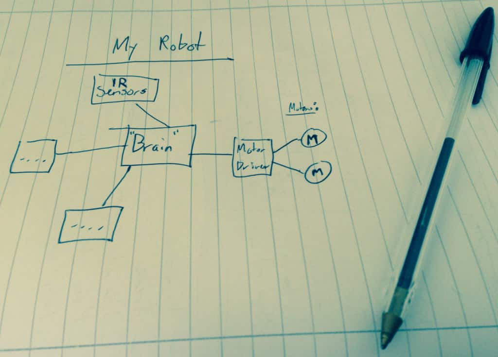
Now create a block diagram to get an overview of your circuit design. For example, if you want to build a robot car you would need motors. And you would need a motor driver. And you would need some kind of “brain” to control everything, like a microcontroller. And probably a few things more.
Get all the different blocks down on paper.

Circuit Design – One Piece At A Time
Now, you will have a block diagram of all the pieces you need to design your schematics.
At this stage, people with experience will be able to move forward a lot faster than people without experience. But that doesn’t mean it’s impossible for beginners. Just take your time and do what I describe here – and you will also be able to build whatever circuit you want.
Start With One Piece
Pick one block from your block diagram.
Let’s say we start with the motor driver for our robot. In many cases, you can find an integrated circuit that has everything you need. And it usually comes with a datasheet that tells you how to use it.
But sometimes there are no suitable chips. So you will have to design the part yourself.
“But I don’t know how to design a motor driver!”, you say. “What should I do?”
The answer to this question is the key. So pay attention now ;)
You learn how to, or you find a circuit design that someone else has made.
It’s that simple. If you want to know how to design a radio transmitter, then learn how to design radio transmitters. If you want to know how to design an amplifier, then learn how to design amplifiers. If you want to know how to design a motor driver, then learn about how to design motor drivers.
This is just how it is. It is like this for me too. For instance, at the moment I have never tried to design a switch-mode power supply. So if I wanted to design that, then I would have to read up on it.
It Doesn’t Have To Take A Lot Of Time
Learning how to design a certain type of circuit doesn’t have to take a long time. It all depends on how much you want to learn. If you just want to find something that works for you, just read enough about the subject to understand what you need. Either from electronics books or the web. Then find a circuit design from someone else that works for you. This doesn’t take much time.
But if you really want to become a master of designing this particular kind of circuit, you would of course have to invest some more time.
Connect All the Pieces
If you have gone through the circuit design process above for all the pieces of your circuit, all you need to do is to connect these parts in one circuit diagram.
So to sum it up – here is how you do circuit design of your own ideas from scratch:
- Define your circuit
- Make a block diagram of all the pieces you need for this circuit
- Design each piece (And if you don’t know how to – learn it)
- Put the pieces together in one schematic diagram
When you have your schematics ready, it’s time to learn how to design circuit boards.
What is stopping you from making your ideas into reality? Post your comments and questions in the comment field below.
Return from “Circuit Design From Scratch” to “Electronic Schematics”
More Schematic Diagram Tutorials

10 Simple Steps to Learn Electronics
Electronics is easy when you know what to focus on and what to ignore. Learn what "the basics" really is and how to learn it fast.

sir,i have a great interest in building and creating electronic project but unfortunately i dont have the proper means to deploy my brain on it due to unavailability of proper knowledge….i am also very much in quest of learning how to make wireless power transmission circuit but as usual lack the knowledge ….could you please suggest me any genuine and good book on electronics and wireless transmision……i wll be very much indebted to u pls reply soon…i am waiting impatiently for your reply..
Hey, sorry I don’t know any good resources on that.
Cheers!
Oyvind
This might help Mouser’s New Technologies. Also, look into how transformers are built. Magnetic coupling isn’t too much diffrent than what goes on inside of a transformer.
only one geinus who can transmit electricity by wireless method The name of the scientist is Sir TESLA search on google you got informations
I apologize, but you are wrong. Nicola Tesla proved that electricity is always going through the air and our bodies.
Look up “QI charging”. This is a form of wireless power transmission commonly found in smartphones. It works with 2 sets of inductors, and you could probably build one.
Ask youtube…
Or Meredith Perry
hi- idea new simple for home
Here is another good course idea for you to make for us. How to join two circuits together.
I enjoyed your course on making circuits, I was a lot slower than you but I eventually got a PBC made (in the software). I bought your book and skimmed through it and it looks great too.
Thanks.
Arnold
Hey Arnold!
Thanks for your comments.
What kind of circuits do you want to join?
Cheers!
Oyvind
hey Oyvind I could make some use from Arnold’s brilliant idea. I want to combine a distance measurer circuit and a laser temperature gun circuit. Any help for that? Cheers!
Hi,
The first thing to do is to find the two circuits. Then we can look at how the first one outputs information, and how you input information into the other one.
If you put the links the the two schematics here, I can try and give you some pointers.
Best,
Oyvind
Am great 4 d wonderful ideas u have been given to me
Dude u made such a great inspiration!
Thanx a lot.
I really like how you make difficult stuff feel simple :-). My passion is all about wireless technology because I feel it is the closest thing we got to magic. My dream would be to build my own set of walkie-talkies or a cellphone. Right now I would love to be able to make (and understand) a wireless on/off switch. I can already do this with infrared technology but I want to learn how to do this with electromagentic waves. You push a button on a remote and light up a small lamp on a circuit a couple of meters away. I know that I need the following basic components:
*Resistors
*Transistors to amplify a signal at the receiving end
*Inductors and capacitators to make the oscillicator
*Power sources like battries and ofcourse a light bulb
I just never understood how to put these guys together in the most simple way. I also don’t know how to match the inductor and capacitator to generate a specific frequency (like 1GHz). If it’s possible I would prefer to avoid mikrocontrollers because that feels like cheating to me. I looked on some circuits for remote car keys but I just got confused everytime and they all seem to use mikrocontrollers.
If you could use your talents in electronics and your teaching skills to help me build and understand a transmitter and receiver, then you are definatley one of a kind.
Thank you in advance!
Kind Regards
Dr Ali
Hi,
Designing a 1 GHz radio transmitter and receiver is not the easiest task to do. I have no idea what level you are at, but to get an overview of what is needed, see this article: http://www.dummies.com/how-to/content/radio-electronics-transmitters-and-receivers.html
The easiest place to start might be to build an FM transmitter: http://makezine.com/projects/super-simple-fm-transmitter/
Cheers!
Oyvind
Hi Dr. Ali
It is possible to make wireless on/off switch without microcontroller. You can use a HT12E encoder and HT12D decoder with a pair of 433 MHZ RF modules.
Dear admin
Thanks for your useful website, but I still have a very huge problem to design even a simple circuit. Would you please explain these steps in a practical way for dummies like me? I mean its would be more clear for me if you define a project and do these level step by step for stupid student. This project could be a “mouse computer with Bluetooth connection, memory, USB port,speaker, wireless for syncing the music and IR sensor to detect the near obstacles and GPS to find the location and inform it to a mobile app beside its original function.”
I appreciate your passion.
Behnam
Thanks for your input, I definitely want to make more examples. Here is an example of ow to build a microcontroller circuit: build-electronic-circuits.com/microcontroller-tutorial-part1/
Cheers!
Oyvind
I would like to build a robotic arm. What components would i need for that?
Hey,
Without knowing anything about your project, here are some pointers: A microcontroller, some motors, maybe some sensors and the arm itself.
Cheers!
Oyvind
What a wonderful article! You made the bulk of circuit design easier for me to grasp! I am slowly learning the process of designing my own circuits, PCB’s, etc. My ultimate goal, as far as circuits go, is to design a microcontroller board that can run the tinyBASIC operating system. This board would need a few connections, such as power, a keyboard, and a screen. The idea is to create the smallest possible PCB, with all the required components, to run tinyBASIC. I have a few microcontrollers in mind, the ATiny85, or the atmega128. Would the ATiny be too puny for tinyBASIC? Any information, or learning material would be greatly appreciated, thanks!
Hey Elijah,
I don’t know tinyBASIC, so you would have to check up on it’s requirements to see what microcontroller you need.
Here’s an intro to microcontrollers that might be helpful: https://www.build-electronic-circuits.com/microcontroller-basics/
Cheers!
Oyvind
Hey Øyvind,
Thanks for this helpful article, it’s really clear and useful for beginners to learn how to design their own schematics. I found your website is full of useful tutorials to help people build electronic circuits. I highly appreciate what you did, which helps us a lot.
Moreover, I’d like to recommend you a free web-based electronic circuit design software – https://easyeda.com
I’ve used it a couple of times and have been impressed by its friendly interface and powerful functions.
It is a free, cloud-based EDA suite, integrating Schematic Capture, Circuit Simulation using ngspice and PCB layout in a web browser GUI. Work can be kept private, shared or made public. Schematics and libraries can be imported from Altium, Eagle, KiCad and LTspice. Files can be exported in a number of formats including JSON. Low cost PCB fabrication is also offered as an option.There are lots of examples on the site and a useful tutorial. https://easyeda.com/Doc/Tutorial/
I think EasyEDA is very suitable for beginners, and also maybe a good tool for you to share your electronics experience.
Thanks. :)
Hai dude, how to get a rose shape deigns through LED lighting’s. I want to gift my girlfrnd for her birthday :)
I have to write a code for that?
Help me out…
Hi, I don’t have code for that I’m afraid.
Best,
Oyvind
please send me the ebooks.
Oh well what can I say. Thank you for giving me some confidence . I hope and wish that I can accomplish my childhood dream. It is not easy to embark on this journey on my retirement age but I am going to give it a go.
Hello,
I am very interested in designing circuits..do you know any resources or any website where I will get questions based on circuit diagram ,block diagram for interview purpose?
Please share
Thanks
Nazia
Hi,
I have worked in electronics for a few years now fixing and making circuits for various purposes from diagrams.
I would like to be able to design my own circuits.
Things such as a circuit that will run on 24 volts, wait for an input, say a connection to 0v, if the input is pulsing on and off then do nothing, when the input stops pulsing then close a relay for 1/2 a second, or so.
Or a circuit that puts 24 v on the output when the input starts to pulse and then removes it 5 seconds after the last pulse.
I have taken these from a model railway sensing a train passing a point and setting signals accordingly.
I help a garden railway system and these would be useful for that but my main wish is to be able to design circuits that can do this sort of thing.
Does your book go anywhere near teaching this sort of thing.
Hi Bob,
I don’t have any books that teach those exact things. But sounds like some of those things can be solved with the 555 timer for example. At Ohmify, you’ll learn to use the 555 Timer and there’s a community forum where you can get help to make whatever project you want to make. Learn more about Ohmify here: https://ohmify.com/join/
Best,
Oyvind
Just curious—do you ever try to combine parts/components from various circuit boards that each ran different (generally older/maybe broken) gadgets… and Franken-board the bits together to make a “new” board?? Even if it’s just to make the new board do utterly odd, silly, and probably useless things??…
I did when I was a kid. Unfortunately the result never did anything. It just short-circuited the power supply. But it could be done of course, if you understand the different circuits you are trying to connect (which I did not back then)
I hope everybody who takes other people’s design and use them credit the originator.