• Skip to main content
  • Skip to primary sidebar
  • Skip to footer

Build Electronic Circuits

Electronics explained in a simple way

  • About Me
  • Blog
  • Products
  • Contact

The Simplest Amplifier Circuit Diagram

May 14, 2013 By Øyvind Nydal Dahl 142 Comments

I have been looking for a good stereo amplifier circuit diagram for a long time. I am not a HiFi geek, I just wanted to build a simple stereo amplifier that could drive some speakers for my desktop computer.

stereo-amplifier-board-layout

All the schematic diagrams that I could find seemed to involve lots of hard-to-find components or you had to use it together with a pre-amplifier or some other amplifier stage. It was always something that made me hesitate.

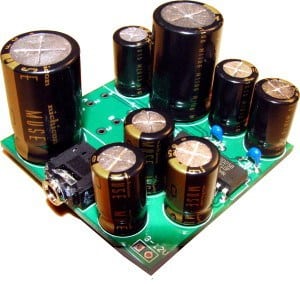
But recently I found this awesome little chip called TEA2025! You only need a few capacitors to make a decent stereo amplifier out of it. It is so simple to build that I put it together on a strip board in just a few hours.

2.5W * 2 Stereo Amplifier

The amplifier circuit diagram shows a 2.5W * 2 stereo amplifier. You can also make a 5W mono amplifier out of it. (Check out the TEA2025 datasheet for more information on that)

Stereo Amplifier Circuit Board

On the input side, you should use a dual potentiometer. A dual potmeter allows you to connect both left and right channel on one potentiometer.

This amplifier is great to use together with some speakers to get sound on your desktop computer. I am thinking of putting one in my kitchen and in my bathroom also. Then maybe hook them up to my home network and stream music from a server =) There are many possibilities when you can make such a cheap amplifier.

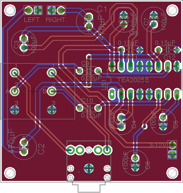
Amplifier circuit diagram and parts list
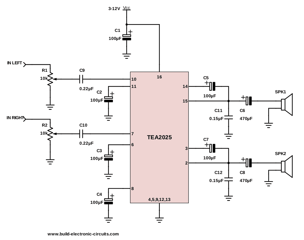
A Stereo Amplifier Circuit Diagram

Parts list

PartValueDescription
C1100µFPOLARIZED CAPACITOR
C2100µFPOLARIZED CAPACITOR
C3100µFPOLARIZED CAPACITOR
C4100µFPOLARIZED CAPACITOR
C5100µFPOLARIZED CAPACITOR
C6470µFPOLARIZED CAPACITOR
C7100µFPOLARIZED CAPACITOR
C8470µFPOLARIZED CAPACITOR
C90.22µFNON-POLARIZED CAPACITOR
C100.22µFNON-POLARIZED CAPACITOR
C110.15µFNON-POLARIZED CAPACITOR
C120.15µFNON-POLARIZED CAPACITOR
TEA2025TEA2025BAmplifier chip
SPKR14-8 Ohm speaker
SPKR24-8 Ohm speaker
R1+R210KDUAL Potentiometer

Total cost of the components (excluding speakers) is about $9. The most expensive component is the potentiometer (about $3-4).

Download Eagle schematics and board layout

Here is the schematics (Eagle), PCB board layout (Eagle) and Gerber files. This board was made to comply with the design rules of Seeed Studio (May 2013).

Stereo-Amplifier-TEA2025-(Eagle)

How Can I Help You?

I want more people to build better and cooler projects. Everyone can improve even if they are complete beginners or have built many circuits from before.

If you love building things with electronics (or would love to), check out Ohmify.

Return from Amplifier Circuit Diagram to Circuit Ideas

Filed Under: Article

Reader Interactions

Comments

  1. Ravi verma says

    June 6, 2014 at 12:28 pm

    Hello Oyvind,
    Thanks for this useful post. i tried this single chip stereo amp. and it worked. but the problem I faced is there is lots of noise also. first i thought it could be a problem with speaker I used (i got my speakers from toy cars,they lied in the said resistance range), so I moved to market available speakers. but the problem persist. Can u suggest me some solution to get get the rid of this noise. any help will be appreciated.
    Thanks and KEEP SOLDERING :)

    Reply
    • admin says

      June 6, 2014 at 12:53 pm

      Hey Ravi!

      Cool to hear that you made the circuit =)

      If the input signal is too high, you will get clipping on the output. This will make the sound noisy.

      So first, check if you have the noise problem when the volume is turned down: (R1+R2) pot turned to a high resistance value.

      Cheers!
      Oyvind

      Reply
      • Ravi verma says

        June 8, 2014 at 5:49 pm

        Thanks for your quick reply,
        I tried your suggested solution and yes the noise is still present at lower volumes.
        And then just for experiment I used higher range speakers(~15 ohm , 5 watt), and the problem was gone :).
        but i also doubt that using these higher higher range speakers ,in a continuous run, the circuit might get damaged. Right?
        And one more thing , i think i should add, I am using USB power supply. As I want to make it completely portable.
        Thanks. :)

        Reply
        • Øyvind Nydal Dahl says

          June 14, 2014 at 8:43 am

          No it shouldn’t be a problem to use higher Ohm speakers. And higher Watt-rating of the speaker just means it can handle more power.

          Maybe your old speakers just had too low Watt-rating…

          Anyway, great that you got it working! =)

          Cheers!
          Oyvind

          Reply
        • Gonzalo Salomon says

          March 29, 2017 at 3:41 pm

          That’s the issue. The IC is probably running out of power. Buy a tablet power supply (5V 2A, for fast charging) and check current consumption with a multimeter. Probably the USB port isn’t providing enough current (check if your motherboard has a port with a higher current limit, since most ports are limited to 300-500 mA). Or buy a 9V rechargeable battery (raising the voltage to get the same power from the supply will give you less current consumption, which is nice running on batteries).

          Reply
    • Alex says

      August 5, 2016 at 2:58 am

      Check the input stage for bad solder joints (can act as diodes hence radio noise). Try a aluminum foil shield to check for external signals that show up as noise. Have an oscilloscope? Check for oscillations in your component layout etc.
      Good luck!

      Reply
    • Ace Axel D. Casas says

      December 12, 2016 at 9:20 am

      Hey sir . Is there any shop have a complete part list for this stereo amplifier ? which is the Layout in PCB ?

      Reply
    • jay says

      June 2, 2017 at 1:04 am

      use battery as power supply. dont use transformers

      Reply
    • Sethumadhavan says

      August 5, 2018 at 12:46 pm

      can you advise me if the out put can be directly given to home theatre
      thanks
      Sethumadhavan

      Reply
  2. wilfredo co says

    June 21, 2014 at 4:29 pm

    i like electronics

    Reply
  3. Jared says

    August 21, 2014 at 3:05 pm

    Hey, thanks for the great schematic, I was actually looking to make an audio amp and this one looks awesome! Although, I was looking for a way to turn this into a 5 Watt mono amp on the datasheet, but couldn’t find anything. :/
    Any help, or am i just being stupid? Should I just use a mono amplifier with similar specs as the tea2025?
    Thanks in advance!

    Reply
    • admin says

      August 21, 2014 at 3:32 pm

      Check out page 4 on the datasheet. The mono configuration is called “Bridge”. It’s the one on the left.

      Cheers!
      Oyvind

      Reply
      • Jared says

        August 21, 2014 at 9:33 pm

        Thanks! I was wondering why that was there, but I just assumed it was a separate application entirely because of the name!

        Reply
      • shilparaj says

        September 1, 2014 at 2:11 pm

        love it…i am just 14..but i am interested in these subject…so thank u man

        Reply
        • Kellyblakmoffat says

          June 9, 2019 at 2:19 am

          i guess u are 19 now

          Reply
      • Anirvan says

        May 3, 2019 at 8:38 pm

        This IC 2025 gets very hot when running on full power. I’m using the bridge version and using 8- ohm speaker on 9 Volts supply. How to fix heatsink on this ic ?

        Reply
  4. Ikenna says

    August 22, 2014 at 3:45 pm

    Pls oyvind,help me here also(i will download your book sooner by grace)can you provide me with a schematic of 4 stage transistor 2.5w mono or stereo audio amp.pls spare the effort to send me the link to this.God bless.

    Reply
    • admin says

      August 22, 2014 at 4:00 pm

      Hey Ikenna

      I don’t have that, but maybe you can find something here: http://www.build-electronic-circuits.com/free-electronic-circuits/

      Cheers!
      Oyvind

      Reply
  5. rocker says

    September 29, 2014 at 7:19 am

    i hav took this ic from my creative speaker and some other parts and made the circuit.but it is not working.i didn’t receive any response from speaker .can u make a video in makin this circuit in breadboard. plz help me

    Reply
    • admin says

      September 29, 2014 at 3:55 pm

      If you have access to an oscilliscope (http://www.build-electronic-circuits.com/sound-card-oscilloscope/), I would recommend you to use that and measure both input and output to figure out what is wrong.

      Cheers!
      Oyvind

      Reply
  6. naresh says

    November 14, 2014 at 5:31 pm

    hello,
    thanks for this

    Reply
  7. Volopo says

    November 20, 2014 at 4:19 pm

    i love boobs =)

    Reply
    • admin says

      November 21, 2014 at 5:28 pm

      I think you’re on the wrong website for that……

      Reply
  8. Angry Jew says

    November 28, 2014 at 2:16 pm

    K lol

    Reply
  9. VAIBHAV says

    December 29, 2014 at 8:13 am

    hye….
    admin,
    what is the maximum input of this circuit?
    and what is the output power for this circuit?

    Reply
    • admin says

      December 30, 2014 at 12:46 pm

      Hi,

      I challenge you to figure it out from the datasheet: http://www.bookly.com/images/TEA2025.pdf

      Cheers!
      Oyvind

      Reply
  10. VAIBHAV says

    December 29, 2014 at 8:20 am

    sorry
    ‘what is the output power ?’ this Que. was ask by mistake
    I know output power is 5watt

    I mean to ask what is current consumption of this circuit?
    or what is power consumption for this circuit?

    Reply
    • admin says

      December 30, 2014 at 12:47 pm

      You can find this info in the datasheet of the TEA2025 chip: http://www.bookly.com/images/TEA2025.pdf

      Cheers!
      Oyvind

      Reply
  11. vinod says

    December 29, 2014 at 12:22 pm

    what is the voltage rating of the capacitors.

    Reply
    • admin says

      December 30, 2014 at 12:52 pm

      I think I used 25V.

      Oyvind

      Reply
  12. zahid says

    February 10, 2015 at 6:06 am

    please tell me the function of pin n0.1 of tea2025b

    Reply
    • admin says

      February 12, 2015 at 8:31 pm

      Not sure what pin that is, but check the datasheet and you will find info on all pins: http://www.bookly.com/images/TEA2025.pdf

      Cheers!
      Oyvind

      Reply
      • Arshad Ayoub says

        April 6, 2015 at 6:46 pm

        Why Do We Use Capacitors in this circuit.. :)

        Reply
  13. tec says

    June 19, 2015 at 9:23 am

    is the voltage rating of all the capacitor 25v.How about 0.15uf capacitor.

    Reply
    • admin says

      June 20, 2015 at 12:14 pm

      25 V should work fine.

      Oyvind

      Reply
  14. tec says

    June 23, 2015 at 1:26 pm

    can i use a 50k ohm dual pot like this:

    http://www.ebay.com/itm/2PCS-ALPS-Potentiometer-RK16-50KA-2-Sound-Controller-/260439149067

    Reply
    • admin says

      June 27, 2015 at 2:45 pm

      Hey, yes that should work fine.

      Cheers!
      Oyvind

      Reply
  15. jackson says

    July 6, 2015 at 7:18 pm

    i have only 10k 6pin potentiometer avaliable….
    so could you tell me how to wire it in above circiut…

    please!

    thanks in advance

    Reply
    • admin says

      August 11, 2015 at 11:51 am

      Hey,

      Check the datasheet of your potentiometer to find out the pin configuration, then match that with the diagram above.

      Cheers!
      Oyvind

      Reply
  16. JPolac says

    July 26, 2015 at 7:17 pm

    Where would I be able to order the 0.22 µF and 0.15 µF non-polarized capacitors online?

    Reply
    • admin says

      August 11, 2015 at 11:52 am

      Hi,

      For example from Jameco: http://bit.ly/1fsYy5h

      Here are some more suggestions: http://www.build-electronic-circuits.com/electronic-component-distributors/

      Cheers!
      Oyvind

      Reply
  17. Shalin says

    August 11, 2015 at 12:50 pm

    What is the diagram software that you used to create these circuit diagrams? Is it creately ?

    Reply
    • admin says

      August 11, 2015 at 3:02 pm

      Hey Shalin,

      It’s Digikey’s Schemeit: http://www.digikey.no/schemeit/

      Cheers!
      Oyvind

      Reply
  18. moses says

    September 24, 2015 at 10:32 pm

    i have a problem with my omega digital karaoke amplifier AV 9715 it make a noise on the speakers i cant hear the sound clearly and its screen dnt display but my main prblm is the sound. Is it the capacitors or can it be the ic 7812 or the sound ic’s on the aliminium plate but they dnt get hot and i also test the voltage on the 7812 input is +- 26v and out is 12v how can u help me i just want 2 knw what to change or replace 4get abt the display i just need the sound first i will appreciate it very much u can email me what 2 do 2 fix it myself on [email protected] please i really need help thanx

    Reply
  19. rashid abbas says

    November 18, 2015 at 7:50 am

    can i plot this circuit on proteous software? i made this circuit on proteous but it’s not working. pls help me

    Reply
    • admin says

      November 19, 2015 at 2:13 pm

      Hi,
      I doubt that you find something that will simulate the chip, if that’s what you are trying to do… I would say just go ahead and build it. No need to simulate.

      Cheers!
      Oyvind

      Reply
  20. Andy says

    November 18, 2015 at 8:35 pm

    Hi Mr.Oyvind,
    I manage to make my amp work but the problem i am facing now is the output volume is too low ,can you please help me?
    I use 50v for all polarized capacitors and 100v for non-polarized ,20k potentiometer and powered by 3v rechargeable battery.Thanks in advance .

    Reply
    • admin says

      November 19, 2015 at 2:15 pm

      Hi Andy,

      If the sound is very low, you can try to increase the volume of your input device. And make sure the potentiometer is at it’s lowest resistance.

      But don’t expect a really loud sound when you’re using only 3V for power.

      Cheers!
      Oyvind

      Reply
  21. Vanowski says

    November 19, 2015 at 9:43 am

    if I don’t have a .15 or .22micro farad. what capacitor can I substitute?

    Reply
    • admin says

      November 19, 2015 at 2:17 pm

      If you can’t get a hold of those capacitor values, try something that is as close as possible. You can also combine capacitors in parallel or series to get other values: http://www.build-electronic-circuits.com/series-and-parallel-circuits/

      Cheers!
      Oyvind

      Reply
  22. Vanowski says

    November 20, 2015 at 12:42 pm

    can I use a 1micro farad for the .22 and .15?

    Reply
  23. Daniel says

    November 25, 2015 at 8:10 pm

    Hey, I built this circuit but I’m facing a problem, I’m not getting output in the 2 channels only in one, why could this be?

    Reply
    • admin says

      December 3, 2015 at 6:48 pm

      Hi, this could be because there are only inputs on one channel. Or it could be that there’s a short-circuit or something on one of the outputs. Try switching the inputs and see if this gives you an output on the other channel.

      Cheers!
      Oyvind

      Reply
  24. DINESH SHARMA says

    December 20, 2015 at 10:54 am

    HI TO ALL AND GOOD NOON,

    IF ANY ONE CAN HELP OUT.

    ACTUALLY I AM LOOKING FOR READY MADE PRINTED CIRCUIT BOARD FOR KARAOKE SYSTEM (AMPLIFIER SPEAKER, IT HAVE USB TERMINAL AND 2 MICROPHONE + RECORDING FACILITY IN THAT SAME AS LIKE (PURE ACOUSTIC 1215 MODEL)
    NEED 2 SET OF AMP. IF ANY ONE IS HAVING THE SAME PLS SHARE THE DETAIL MY NO IS 9004049095.

    Reply
  25. assura sugih says

    December 20, 2015 at 3:29 pm

    hi , i’m still curious , when use 9 volt of power is the ic become hot or not ?

    thanks

    Reply
    • admin says

      December 23, 2015 at 12:02 pm

      Hey,

      I think it will become a bit hot yes. But not more than it can handle.

      Cheers!
      Oyvind

      Reply
  26. Madhukar Shah says

    February 14, 2016 at 7:57 am

    I have purchased 600W sterio amplifier with USB and mic-2 kit i want to understand bass treble and volume wiring in 6-pin pot

    Reply
  27. Valentin Andrei Banu says

    April 4, 2016 at 10:49 pm

    I have just finished asembling the bridge version and I am impressed of the quality and the power of this IC!

    Reply
    • admin says

      April 5, 2016 at 8:05 pm

      Yeah, it is pretty good, right? I’m often using it to play music at home.

      Oyvind

      Reply
  28. R.j. says

    April 8, 2016 at 11:01 am

    Hi, im up to build this little amp for my desktop pc (the built-in speakers are just terrible)
    I haven’t seen the lay out yet (as i don’t own any software for that purpose) but there is a pic at the beginning of the topic that brought a simple question to me:

    Is the layout drsignes to be used with a double sided copper board .?

    Thank you :)

    Reply
    • admin says

      April 15, 2016 at 8:32 am

      Hey,

      The design I created was double-sided. But it shouldn’t be too hard to make a single-sided design if you want to do that.

      Best,
      Oyvind

      Reply
  29. edwin says

    May 22, 2016 at 10:27 pm

    i need your e-book

    Reply
  30. Alberto says

    July 22, 2016 at 11:52 pm

    Resonating on the curcuit

    Reply
  31. Tayaan Emmanuel says

    August 21, 2016 at 2:40 pm

    I use to make amplifiers from the internet and it makes little hmmm noise when the volume is attached. Please may know what could the course

    Reply
    • admin says

      August 22, 2016 at 5:53 pm

      Hi,
      The incoming signal could be too high. The amplification could be too high. There could be noise in the incoming signal.

      Best,
      Oyvind

      Reply
  32. sandeep unnichery says

    August 26, 2016 at 10:15 am

    haai brother my name is sandeep from Kerala I made this amplifier, no any problems ,now I am using this amplifier to my headphones, brother you are great ,don’t damage ur health ,take care bro thanks sandeep

    Reply
    • shubham says

      August 30, 2016 at 3:00 pm

      How much voltage rating should have 100uf capacitor for this circuit. Can i use 25v capacitor???

      Reply
      • shubham says

        August 30, 2016 at 5:54 pm

        Can i use single sided pcb

        Reply
      • admin says

        August 31, 2016 at 4:58 pm

        Yes, 25V should be fine (I think).
        And yes, single-sided pcb works fine.

        Best,
        Oyvind

        Reply
  33. tharun says

    August 29, 2016 at 11:31 am

    hello sir this tharun I just want to create tv signal jammer in that many circiuits are there I just want to solve and create a tv jammer or hotspot jammer I will buy what ever u say

    Reply
  34. Tithira senaratne says

    September 9, 2016 at 3:47 pm

    can we use 50v capacitors for the circuit ,and how to generate groove

    Reply
    • admin says

      September 12, 2016 at 11:56 am

      Yes you can. I don’t know what groove is.

      Reply
      • Tithira senaratne says

        September 13, 2016 at 8:50 am

        thanx

        groove means
        sub woofer effect

        Reply
        • admin says

          September 13, 2016 at 9:21 am

          Ah ok. So you want more bass? With this circuit my best guess would be to add a low-pass filter on the input side. Haven’t tried it though, so I don’t know how the effect will be.

          Reply
          • Tithira senaratne says

            September 14, 2016 at 6:51 pm

            thank you so much.i’ll try.

  35. Sanjay Lalwani says

    October 5, 2016 at 4:03 pm

    Hey, how can I add the input to the speaker? I am a complete beginner to it and don’t know how to do it. Also, can you help me with the Potentiometer?

    Reply
    • admin says

      October 8, 2016 at 11:39 am

      Hi,
      The input does no go to the speaker. The output goes to the speaker.
      You can read about the potentiometer here: http://www.build-electronic-circuits.com/potentiometer/

      Best,
      Oyvind

      Reply
  36. ezzhar says

    October 8, 2016 at 9:48 am

    hye admin…can i use 9v bttry for this ciruit….thanks

    Reply
    • admin says

      October 8, 2016 at 11:39 am

      Yes you can.

      Reply
  37. it'z bilal says

    October 16, 2016 at 12:50 pm

    Why u was use soo many cap in circuit…..??

    Reply
    • admin says

      October 19, 2016 at 12:59 am

      For filtering or to avoid oscillations. You might be able to skip some of them, depending on your power source.

      Best,
      Oyvind

      Reply
  38. Vengatesh says

    October 30, 2016 at 2:51 pm

    I have a transformer 230/12V , with this can I give supply power for the chip after converting it to DC? Is the circuit is able to withstand the power supply?

    Reply
    • admin says

      November 4, 2016 at 6:46 am

      If you have the correct DC voltage in, the circuit is fine as long as the power supply can prove enough current.

      Reply
  39. Nhlaka in South Africa says

    November 12, 2016 at 11:23 am

    Hello Oyvind,

    Thanks for this website. It is very helpful. I want to try making a portable audio amplify for devices like cellphones, mp3 player, etc. with an SD card slot and a USB charging port for a 3.7 voltage battery.
    But I haven’t got a faintest idea where to start with a circuit. Any clue Oyvind would be really appreciated.

    Reply
    • admin says

      November 14, 2016 at 7:51 am

      Hi,

      Well, I guess this article is a start. Here you build the amplifier. For the other parts of the project I don’t have any articles unfortunately.

      Reply
  40. Idrys says

    December 28, 2016 at 9:27 pm

    wishing you success. buy how am I make local transformer

    Reply
  41. Conrado says

    January 12, 2017 at 5:50 pm

    If I want to make it Mono, I ignore one of the inputs?

    Reply
    • admin says

      January 13, 2017 at 7:39 am

      Yes you can. But if you want more power, check the datasheet for how to connect the outputs in mono-setting.

      Best,
      Oyvind

      Reply
  42. Clayton Benignus says

    February 3, 2017 at 4:08 pm

    I need to boost a signal sixfold before I divide it by 6 to send to 6 different destinations. Can this be done with an LM386? Also, I do not seem to be able to make the LM386 specs give me hints on how to do it.

    Reply
    • admin says

      February 15, 2017 at 8:55 am

      The amplification part should be possible yes. Check out page 5 in the datasheet for circuit examples:
      http://www.ee.ic.ac.uk/pcheung/teaching/DE1_EE/Labs/LM386.pdf

      Best,
      Oyvind

      Reply
      • Clayton Benignus says

        April 9, 2017 at 3:41 am

        Clearly I need to learn how to read a spec sheet. Any pointers?

        Reply
        • admin says

          April 17, 2017 at 4:51 pm

          On page 5 you’ll find “Typical Applications” with several circuit diagrams. Connect the circuit diagram as in the one marked with “Amplifier with Gain = 20” and you get 20-fold the signal.

          If you need exactly 6, you can play a round with the resistance on the input.

          For splitting the signal, you can use resistors for basic splitting. Google “signal splitter circuit” to see some examples

          Reply
  43. Utkarsh Verma says

    February 11, 2017 at 3:58 pm

    Hello, I am facing a strange problem with this circuit. The whole circuit wired up this way results in one working speaker while the speaker connected to pin 2 and 3 doesn’t work. I am powering this circuit 12v just so you know. When I was tinkering with the circuit, I found that removing the 470uF capacitor connected to non working speaker and shorting the wire, the speaker starts receiving sound but now the output is way too noisy. I tried replacing the capacitor but nothing happened. Do you have any idea?

    Reply
    • admin says

      February 15, 2017 at 8:56 am

      It could be a broken capacitor…

      Reply
      • Chukwu Anointing says

        June 24, 2017 at 11:13 pm

        Thanks sir you are really doing, but I plead your indulgence to ask you of how to build a 2000W stereo power amplifier

        Reply
  44. sevelin says

    March 8, 2017 at 10:11 am

    hi i tired to build this aplifier system but the problems is low sound

    Reply
    • admin says

      March 9, 2017 at 5:11 pm

      Check the sound level of your music source.

      Best,
      Oyvind

      Reply
  45. ananta says

    March 17, 2017 at 5:37 am

    hlww..i made this circuit and it works great..thank a lot… :)
    i have a question..can i use two outputs in one speaker??
    if i can then how to add??

    Reply
    • admin says

      March 20, 2017 at 11:36 am

      Cool!

      Yes you can. Check out “Bridge application” on page 4 of the datasheet:
      http://www.bookly.com/images/TEA2025.pdf

      Best,
      Oyvind

      Reply
      • Chukwu Anointing says

        June 24, 2017 at 11:28 pm

        How can I buy your textbook sir, for I really neef it.

        Reply
        • admin says

          June 26, 2017 at 5:08 pm

          You can find one here:
          https://www.build-electronic-circuits.com/products/ebook-2nd-edition/

          Best,
          Oyvind

          Reply
  46. General says

    March 27, 2017 at 4:55 pm

    Hy guys my problem is i dont know where to buy those printed circuit boards i live at durban.so idnt know where to find those boards for soldering and how much is it?

    Reply
  47. Kirk says

    March 27, 2017 at 10:36 pm

    This is a really cool thing! I am new to electronics so I have a stupid question. How can I connect the two inputs to my laptop if I build this on a breadboard?

    Reply
    • admin says

      March 28, 2017 at 8:54 am

      Hey Kirk,
      You need to use an audio mini jack to plug into your laptop. Mini jack on one side, loose wires on the other side to plug into your breadboard.

      Best,
      Oyvind

      Reply
      • Kirk says

        April 8, 2017 at 2:15 am

        Thank you so much for the reply! Another problem I encountered is the TEA2025 chip seems to be a pretty old version and many electronic shops are out of stock. Could you tell me where I can buy it since I wanna start building it in a week? Thanks!

        Reply
        • admin says

          April 17, 2017 at 4:43 pm

          By using findchips.com I find that Quest Components has it:
          http://www.findchips.com/search/tea2025

          But in general it’s getting really hard to find. I’ll update this article soon with a new circuit with easy-to-find components (Hint: LM386)

          Best,
          Oyvind

          Reply
          • nirban shangkor says

            May 21, 2017 at 3:56 pm

            I wanna make an amplifier use for 6 spkr..how can do it..please give sugges..and circuit

  48. Eduwmy says

    May 17, 2017 at 10:12 am

    I made this circuit and worked perfectly well with only one input and output ,the other output produced noice ,i also made a pre amp ad on it and i made à microphone loud speaker .thanks

    Reply
  49. llewelyn says

    June 5, 2017 at 2:27 am

    hi
    This is a great little amp, but im working on a pet project for sound in my car involving, among others, this TEA circuit.

    Here is my idea for ‘poorman’s’ radio:

    I found various completed circuits out of hi-fi systems and portable radios. Im trying to use them all in my car as a complete built in system, without using a radio that can easily be stolen.

    I have wireless bluetooth speakers that came with my phone that i want to put front in-dash, a TEA2025D circuit from an old treadmill and a TEA2025 that i got from an old hi-fi.

    Individually, each one has great power, but i want to make them work together from one source, an auxilliary input and/or, the bluetooth link. Im only using my phone as the music player.

    When i connect the one with the other, a lot of sound disipates or alot of static comes through, giving me the idea that one or the other is getting too much power or drawing too much.

    i can give easch one its own input from the potentiometer, but that o lot of extra wiring in the car as the layout requires the one circuit to be in the back, powering those speakers.

    Is there a way i can link them up together?

    Please give me some advice. Youre welcome to have a good long laugh at my expence first, but my reasons for this idea is not to spend any money on the system and still get powerfull sound, while making sure nobody is tempted to break into my car when they see a radio in the dash. FYI, ive lost 4 radios in 3 months through crime and im done buying new radios.

    Keep in mind, ive collected the proper size speakers for every amp circuit’s rated output.

    Hope you can help

    Thank you

    Reply
  50. Mubashar iqbal says

    June 23, 2017 at 11:42 pm

    sir
    how can add a subwoofer or Base in this circuit
    plz gide me

    Reply
  51. Kumah Andrews says

    June 29, 2017 at 6:44 pm

    Pls my problem is with the schematic,
    Between C5 and C11 you made C6 to pin 15 pass through. Same thing applies to C7, C12 and C8. The question is; are they interconnected on those points. I am soldering but when I reached there I’m confused, so please help me now.
    Thanks for your effort

    Reply
    • admin says

      July 3, 2017 at 1:32 pm

      Hi,

      Yes they are all connected. If you look closely there is a little dot where they all intersect. This dot means that they should be connected.

      Best,
      Oyvind

      Reply
  52. Kumah Andrews says

    July 1, 2017 at 5:11 pm

    Thanks for your help. I’m able to make it…but I want you to help me build one that has two TEA2025B. Pls help me with the schematic or circuit. Thanks

    Reply
  53. Peter says

    August 1, 2017 at 5:56 am

    Please iam okonwo peter obinna a Nigerian I love electronics but don’t know how to follow it up . I enjoy seeing constructed circuits .initially I thought they were been made by ghosts I never knew one can make something wonderful like that . please admin is there a way I can start making circuit’s and see it work PLEASE although iam a higher institution student but academics in my country is very hard because one has to combine so many hustles just to make ends meet

    Reply
  54. Gene says

    August 14, 2017 at 7:54 am

    I just want to know what is input and output there before potentiometer?

    Reply
  55. Steve Smock says

    October 13, 2017 at 11:41 am

    Hi,
    Wow! Nice and useful post. Can I use this Amplifier TEA2025D – https://www.icrfq.com/part/2430187-TEA2025D.html instead of TEA202?

    Thanks.

    Reply
    • admin says

      October 17, 2017 at 11:54 am

      Hi, yes you can!

      Oyvind

      Reply
      • Steve Smock says

        October 18, 2017 at 8:04 am

        Hello, Oyvind,
        Thanks for your reply.

        Reply
  56. Asang says

    October 31, 2017 at 5:23 pm

    can i use 0.1 instead of 0.15 cap?

    Reply
    • admin says

      November 2, 2017 at 3:07 pm

      I’m pretty sure that should be okay, yes.

      Best,
      Oyvind

      Reply
  57. Kevin P Chacha says

    December 16, 2017 at 1:56 pm

    what is Tea2025?

    Reply
    • admin says

      December 18, 2017 at 4:21 pm

      It’s the chip I used for this project.

      Reply
  58. Sunny says

    February 5, 2018 at 5:36 pm

    Sir…can..i.have.ur…no.plz

    Reply
    • Sunny says

      February 5, 2018 at 6:08 pm

      Plz…sir.

      Reply
  59. YOGESH says

    February 24, 2018 at 8:40 am

    It is a good circuit for amplifier, but you have not mentioned the voltage of capacitors (Polarized) from C1 to C8. Please mentioned voltage of capacitors to make the circuit useful for beginners….
    Thanks..

    Reply
    • admin says

      February 27, 2018 at 5:37 pm

      25V and up should work fine.

      Reply
  60. patrick says

    May 8, 2018 at 5:48 pm

    I am happy to come across this site, I am somebody who like electronic but don’t have someone to teach me, please I need your help. Thank you.

    Reply
  61. rasika says

    May 9, 2018 at 12:38 pm

    please any one share the vero board disign with circuit diagram

    Reply
  62. rasika says

    May 9, 2018 at 12:38 pm

    please share the vero board design

    Reply
  63. Maa says

    June 23, 2018 at 12:33 pm

    Are the potentiometers needs to be a Dual Potentiometer(6 pins) or can I use 3 pin potentiometer?

    Reply
    • admin says

      June 25, 2018 at 3:05 pm

      Each channel needs 3 pins. So for the stereo amplifier you need a dual pot. But if you build a mono amplifier, you only need a standard pot with 3 pins.

      Reply
  64. Zach Foreman says

    July 25, 2018 at 2:16 am

    Hello im very new to all of this. I recently took apart my CRT tv and was able to salvage a TDA8580J chip and speakers . I cant seem to find any schematics for this chip. Could you help?

    Reply
    • admin says

      July 25, 2018 at 7:54 pm

      Hi Zach, you can schematics in the datasheet: https://www.nxp.com/docs/en/data-sheet/TDA8946AJ.pdf

      Check out page 14 (Application information)!

      Best,
      Oyvind

      Reply
  65. Ahonse Isaac says

    August 12, 2018 at 7:19 pm

    I did not get capacitor 0.22uf so I use 221in place and 0.15uf , I use 181 but I did not get any sound coming. Please what should I do.

    Reply
    • admin says

      August 15, 2018 at 8:27 pm

      Those capacitors are there for filtering. But using the values you used should still give you sound, so there must be something else wrong.

      Reply
  66. colch says

    November 25, 2018 at 12:35 pm

    sir what is the voltage value of all the capacitors ? thank you for answer

    Reply
  67. venus says

    November 25, 2018 at 12:38 pm

    sir what is the voltage value of all the capacitors? thank you in advance

    Reply
  68. Nsik says

    May 8, 2019 at 9:46 am

    I made the amp and its working fine. Thanks for the post.

    Reply

Trackbacks

  1. TEA2025 – Simple 2.5W Audio Stereo Amplifier | Make, Electronics projects, electronic Circuits, DIY projects, Microcontroller Projects - makeelectronic.com says:
    May 23, 2013 at 5:56 pm

    […] TEA2025 – 2.5W Audio Stereo Amplifier – decipher again about this scheme specify […]

    Reply
  2. Speaker amplifier circuit | Pearltrees says:
    July 23, 2015 at 9:42 am

    […] because I had it lying around. Costs: All together, I spent around €100,- for the whole project. The Simplest Audio Amplifier Circuit Diagram. I have been looking for a good stereo amplifier circuit diagram for a long time. I am not a HiFi […]

    Reply
  3. Simple DIY Electronics Circuits « Microcontroller, Robotics, Circuits & More.. says:
    October 12, 2015 at 4:57 pm

    […] Check out the full project here: Simple Amplifier Circuit […]

    Reply
  4. How Amps are Made - DIY Step by Step Instructions says:
    August 31, 2017 at 12:24 pm

    […] diagram will show the location of each component in the amp. It is basically a map. Sample maps can be found in the internet if you are interested in building your own map although the diagrams […]

    Reply

Leave a Reply Cancel reply

Your email address will not be published. Required fields are marked *

Primary Sidebar

Most Popular:

  • Basic Electronic Components Used in Circuits
  • Blinking LED Circuit with Schematics and Explanation
  • Learn Electronics With These 10 Simple Steps
  • How Does A Capacitor Work?
  • How Transistors Work - A Simple Explanation

Search:

Privacy & Cookies: This site uses cookies. By continuing to use this website, you agree to their use.
To find out more, including how to control cookies, see here: Cookie Policy

Footer

Site:

Home
About
Blog
Contact

Social:

Facebook
Twitter
YouTube
Google+

Copyright © 2019 · Dahl Technology · Terms and Conditions