To complete today’s part of the microcontroller tutorial – I have doubted myself, I’ve burned my finger and I’ve received a surprise bill from the customs.
But all in all, I’m very happy with the result. I made it work. And I love the feeling I get when I make something work!
We are now at part 5, the final part, of the microcontroller tutorial. Up until now we have learned:
- What a microcontroller is
- How to select a microcontroller
- How to design a circuit with the microcontroller
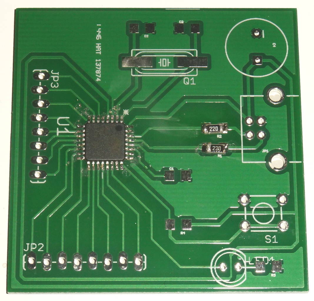
- How to create a circuit board from our circuit
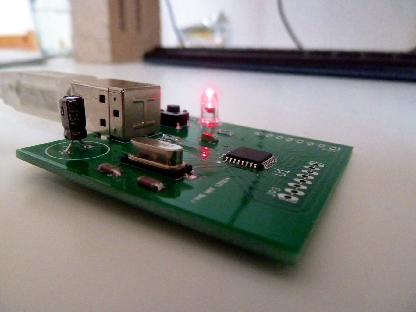
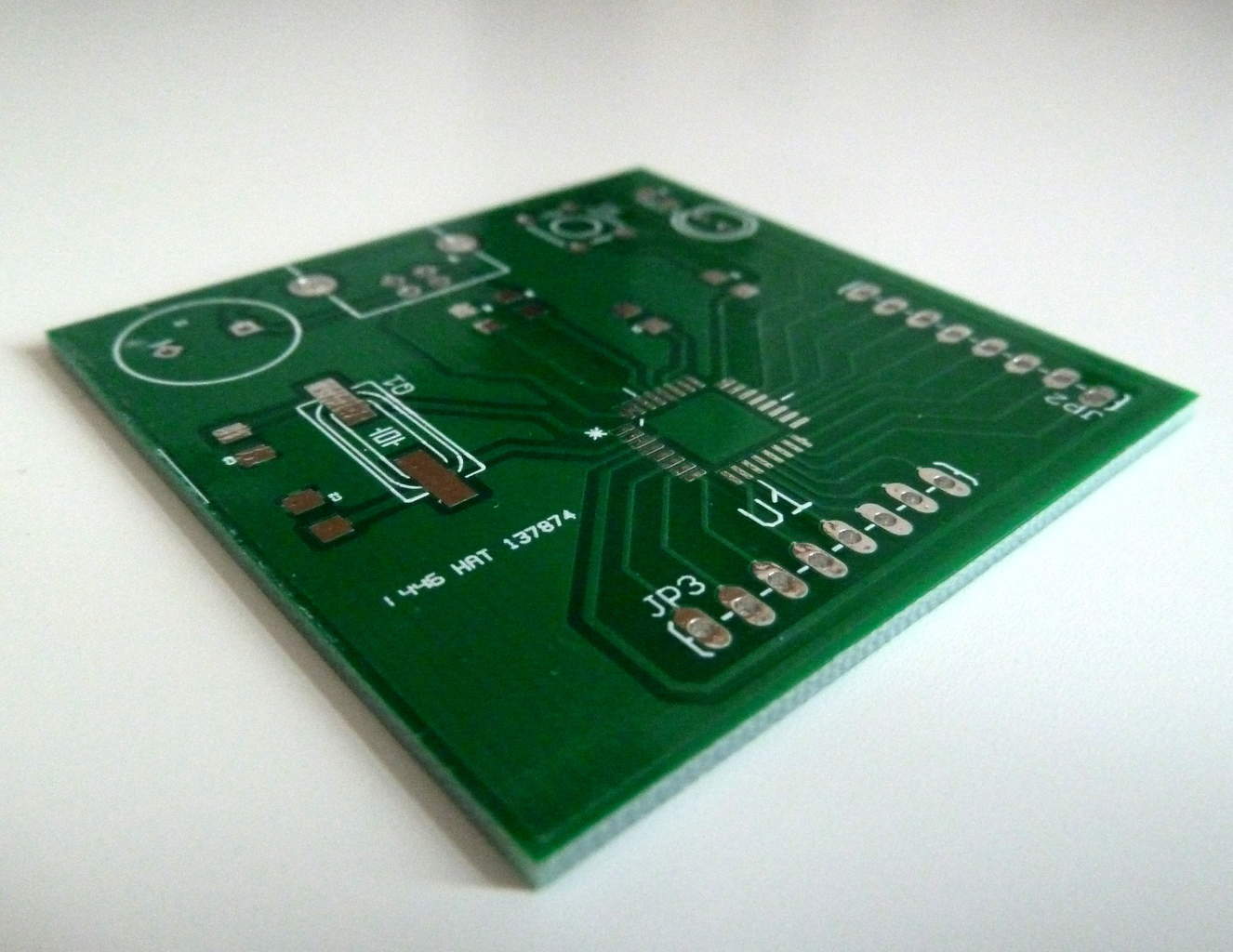
I have just received the boards I ordered in the previous part, and today we are going to solder the board and program it.
Soldering The Board
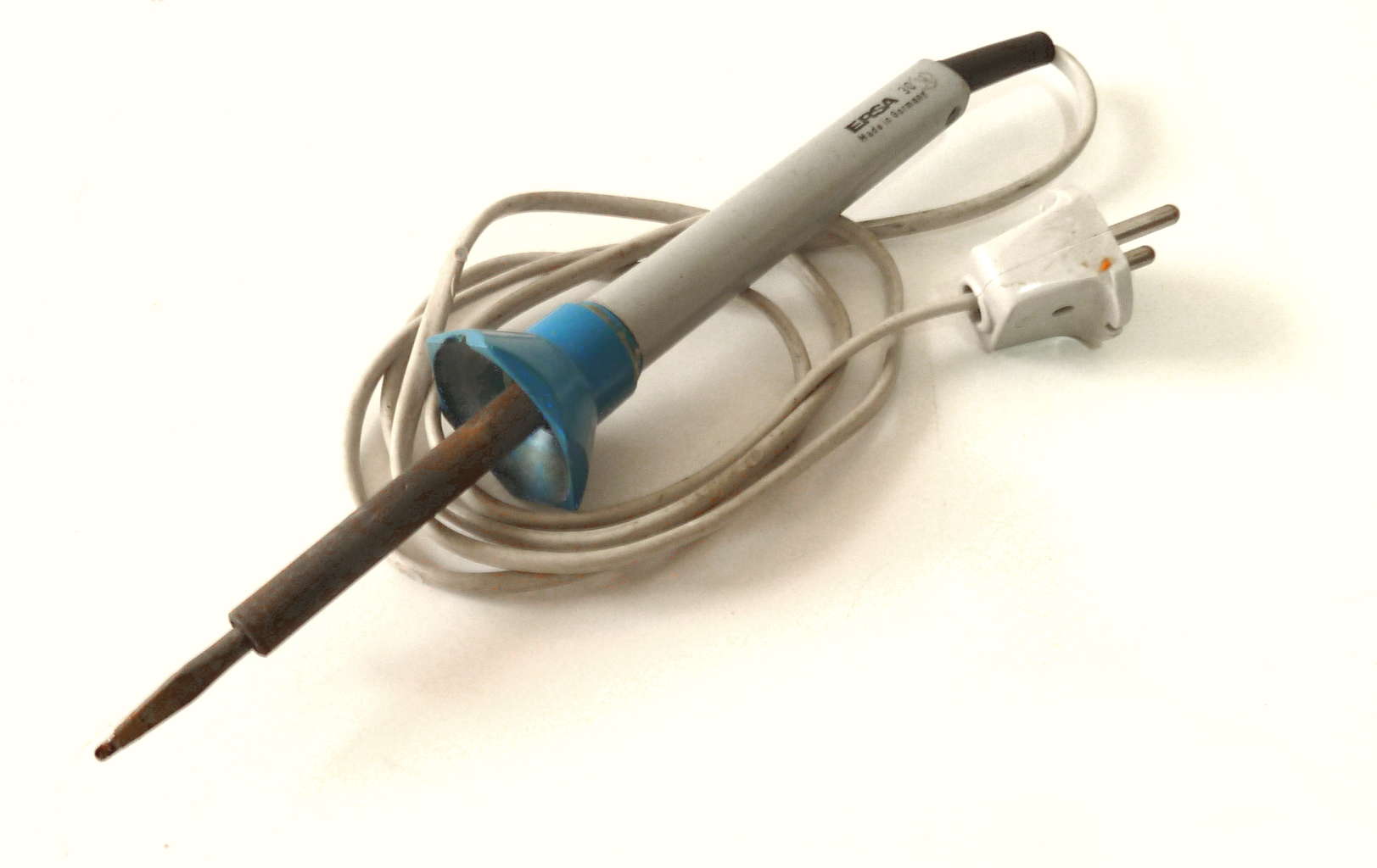
To solder the board – I am going to use my old Ersa 30 soldering iron. The tip of it is a bit big, so it’s really not the ideal tool to use.
But it’s what I have on my desk right now.
And it’s also a way for me to show you, that you don’t need any fancy equipment to make this circuit.
You can make this circuit at home.
Download the Microcontroller Tutorial
A step-by-step guide on how to make a microcontroller board you can build at home using standard hobby tools.
Because I wanted to put everything on one side, I chose to use mostly SMD (Surface Mount Device) components when I designed the circuit board.
So to solder this, I’m going to use the techniques from my smd soldering article.
Soldering the Microcontroller Chip
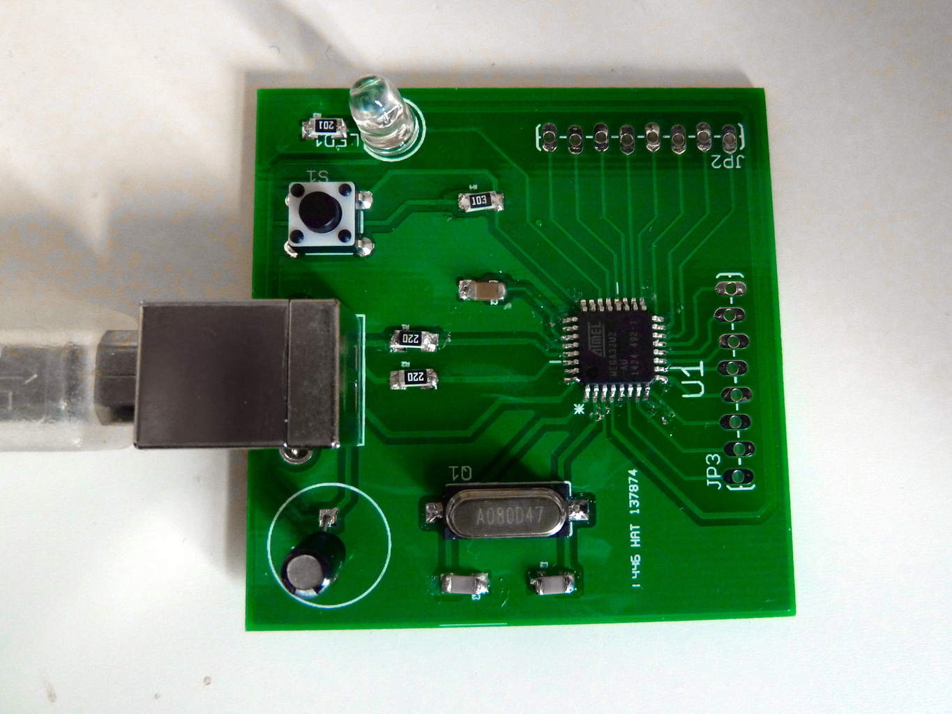
Since the microcontroller chip was the most difficult thing to solder, I started out with that one.
First, I added some solder to one corner pad. I placed the chip carefully, using a pair of tweezers. And I made sure that all the pins were placed correctly over their pads.
Then, while holding the chip in place with the tweezers, I placed the tip of my soldering iron onto the pin and pad of the corner where I already added the solder – making the solder melt.
I removed the tip, and let the solder cool for a second. The chip was in place. Now, all I needed to do was to apply a bit of solder onto each of the pins, to make them stick to the pads on the board.
This was a clumsy process with the thick tip of my soldering iron. But, by keeping my cool and being patient – I was able to solder all the pins onto their pads. We only need a tiny bit of solder for each pin.
As you can see from the picture above, soldering with the large-tip soldering iron was a bit messy. But it doesn’t matter – as long as it works.
Soldering the Other Components
After I’d managed to solder the chip, the other components were easy. I might not have gotten them perfectly aligned, but it wasn’t that bad either.
Testing the Circuit
The ATmega32U2 chip comes with a pre-programmed boot-loader that should make it appear as a USB device when plugged into a computer.
After everything was soldered, I SHOULD have inspected the solder joints closely with a USB Microscope or something. It’s smart because if there are any short circuits caused by a tiny little solder blob somewhere, we could damage our circuit.
But I didn’t have one nearby – and I was super excited to see if it worked. I’m kind of like a child waiting to open my presents on Christmas in this situation. I can’t always make myself do what is smart to do. I’m just too excited to see if it works. So instead I just looked extra carefully at the USB pins, to see if they at least seemed to be properly soldered.
I plugged it into my USB port and…
…nothing happened.
I was a bit disappointed for a brief second. Until I realized that nothing was supposed to happen. I only had one LED on the circuit, and it was connected to an IO pin.
So I needed to check if it showed up as a USB device on my computer.
And it did! Wohooooo!!
Programming the Microcontroller Circuit
Now that I knew the USB part was working, it was time to program the circuit with some code.
I’ve written about microcontroller programming before.
We need to:
- Create program code
- Compile code into machine code
- Upload code onto our board
Program code
To make a simple test, I created a blink-LED code. It does nothing more than blink the LED on the board.
Here is the code I used:
#define F_CPU 1000000 // The chip runs at 1 MHz as default (even if you are using a 8MHz crystal)

#include <avr/io.h>
#include <util/delay.h>

int main(void)
{
    DDRC = (1<<PC7);		//Sets the direction of the PC7 to output
    PORTC = (1<<PC7); 		//Sets PC7 high

    while(1)
    {
        _delay_ms(500);		//Wait 500 milliseconds
        PORTC &= ~(1<<PC7);	//Turn LED off

	_delay_ms(500);		//Wait 500 milliseconds
	PORTC |= (1<<PC7);	//Turn LED on
    }

    return 0;
}
Compile the program
I saved the code in a file called blink-led.c. Then, I used a tool called avr-gcc to compile the code.
Because I am using a Linux machine with Ubuntu, this is very easy to do (for Windows, check out Win-AVR). First, install the application by opening a terminal window and typing:
sudo apt-get install avr-gcc
Then you can compile by typing in these two commands:
avr-gcc -mmcu=atmega32u2 -Os blink-led.c -o blink-led.out
avr-objcopy -j .text -j .data -O ihex blink-led.out blink-led.hex
Now we have a file – blink-led.hex – that we can upload to the microcontroller.
You can find more information on the commands here.
Upload Program Onto Board
To get the program onto the board I used dfu-programmer. First, install it:
sudo apt-get install dfu-programmer
First, we need to erase the old memory (note that this is important – even if your flash is blank):
sudo dfu-programmer atmega32u2 erase –force
Then we flash the microcontroller with our program:
sudo dfu-programmer atmega32u2 flash blink-led.hex
I needed to unplug it from the USB, then connect it again…
And it worked!
The Next Steps…
I’m gonna play around with the circuit for a little bit, then I’ll probably post some fun projects you can make with it.
Until then, I urge you to read all the parts of the tutorial to get a full understanding:
- Part 1: What is a microcontroller?
- Part 2: Choosing a microcontroller
- Part 3: Designing a microcontroller circuit
- Part 4: Creating a PCB for your circuit
- Part 5: Soldering and programming the circuit
Now, after reading the whole tutorial – what are you struggling with? Post your questions and comments below.
More Microcontrollers Tutorials
Download the Microcontroller Tutorial
A step-by-step guide on how to make a microcontroller board you can build at home using standard hobby tools.
I have an 80+watt soldering that I use for all my soldering needs, however I am a bit wary of using it on micro circuit chips such as the surface mount you have used in the project above, what fear is overheating the pins and damaging the internal components of the chip. Are my fears warranted or are these chips more resiliant than give them credit for? Also, when initially signed up, was told I would receive a “free” ebook, have yet to receive any such book. I do enjoy the news letters imensely as it only motivates me to want further get into electronics. Another thing, have tried sorcing local supliers of PCBs but have not found such, do however have a supplier of copper clad boards that one can “draw” your own circuits on and etch the excess copper of using an etching fluid. Would this work as well for most projects?
Hi,
When you confirm that you want to be signed up you should be redirected to a page with a link to download the ebook. If you didn’t see it, just send me an email and I’ll guide you to finding it.
You are right that you can damage a chip with too much heat. Check the datasheet of the chip to get the details of what it can handle.
Etching you own PCB’s will work yes. But it is a bit more work with adding vias, and creating double sided boards.
Cheers!
Oyvind
Hi oyvind, I’ve been reading ur newsletter for some time and struggling myself whether to buy ur ebook or not…
FYI, I’m mechanical background and are very enthusiasm in electronics..I only manage to design some simple circuit with a combinations of few switches, relay, contactor and some other electronic components which is used to test some module of the machines..what I’m interested is using micro controller and do somemprogramming code in order to design a more complicated board in order to impress my boss..but I have no knowledge about programming and not sure whether ur book will have a step by step and clear enough tutorial for me to refer?
Eg how to declare variable…initialize the code..what is the function of the code line by line and details explanation on it..
U can reply to my gmail if you have any doubts to be clarify…thanks
Rgds,
Kuam
Hi Kuam,
Great to hear that you are interested in learning about microcontrollers. But my eBook «Getting Started With Electronics» does not cover the topics you are looking for.
This tutorial should be a good starting point instead. And you can post in the comment field if you have any questions.
Cheers!
Oyvind
Hey! I started soldering this together today and I’ve encountered a problem: My board has no contacts on the reverse side (for the through hold components.)
For the big capacitor, the tact switch and the LED I solved this by soldering them on the top side of the board, but I can’t do that with the USB socket as it’s contacts are buried underneath it’s casing. I tried soldering it on the bottom side, but the holes are too small for the solder to wick through and get to the traces to make a positive contact.
Any advice? All I can think of is to countersink the holes very carefully with a drill from the bottom side to make them large enough for the solder to get through, but I’m sure there must be a better way.
Hey Peter!
I have never encountered that problem, so I have no hands-on experience with it. Maybe you can find some thin wires that you solder on the pad before placing the USB connector. Then run these wires through the holes together with the USB pins….
I hope you find a good solution!
Cheers!
Oyvind
I think that’s actually a better solution than the one I came up with: In the end I suspended the USB port so the ends of the connectors were on the top of the board rather than poking through to the other side, then I soldered them unto place on the top side underneath the port. It was hard, but I got a positive signal so I’m happy :)
Hi again, I got the board soldered but I’m having a little trouble compiling the software. The package avr-gcc doesn’t seem to exist, but gcc-avr does so I installed that instead. When I went to compile it couldn’t locate the include files. Do you know where these are usually installed to? Can I edit the .c file to give a path to them like “#include ” or do I have to do everything from that folder?
Hi
The include files are from avr-libc (http://www.nongnu.org/avr-libc/)
If you install avr-libc, you shouldn’t need to modify the code.
I don’t understand how you found gcc-avr, i tried to Google it and only avr-gcc appears….
Cheers!
Oyvind
Thanks, I’ll try that. Here’s the package I installed: https://launchpad.net/ubuntu/+source/gcc-avr
I finally got my USB A to B cable today and unfortunately my device isn’t showing up as a USB device :/ Not in Ubuntu’s file manager thing anyhow, might have a poke around in terminal later to see if it’s hiding somewhere.
Thanks anyhow for all the help.
Compiling worked perfectly after installing avr-libc, thanks :)
Had a couple of false starts with flashing the hex, but it works perfectly now. Thanks for all your help :)
Woho! Great to hear =)
Oyvind
sir iam new here ……
i want to know that how i connect the component with a microchip that how i khow where i need to connect a resister or a capaciter please help sir thanks in advance my email is [email protected] and my phone number is 03149053597
Hi,
Maybe this article can help: https://www.build-electronic-circuits.com/electronics-for-beginners/
Cheers!
Oyvind
hello sir, I also have the same question as asked above by zain ul islam.
And I also want to ask how to decide that how much voltage and power is to be given to the various components in a circuit ,like somewhere we use 9V battery,somewhere 11V or we use 10 microfarad capacitor somewhere and somewhere we use 5microfarad capacitor. likewise somewhere we use 1k ohm resistor or somewhere 10k ohm…
how to decide such things in a circuit.
please do reply sir my email I’d is [email protected]
Hi,
Maybe this article can help you too: https://www.build-electronic-circuits.com/electronics-for-beginners/
Cheers!
Oyvind
Instead of compiling using the software listed and using a separate software to upload to the microcontroller, could you simply use the Arduino IDE to upload to this or not since it technically isn’t an arduino?
Hey,
To use the Arduino IDE, the chip needs the Arduino bootloader. If you are able to get the bootloader onto the board, you can use the Arduino IDE. I have never tried to do it, so now sure how to go about it. But a quick google search gave this discussion, that you might find useful:
http://forum.arduino.cc/index.php?topic=121371.0
Cheers!
Oyvind
Hi, just connected the board today but it doesn’t show up in the USB connection list. There is power on the board, but is there a way to check whether the D- and D+ pins are doing what they should be doing?
Thanks
Hey,
What operating system are you using?
If you are using linux, you can try the command ‘dmesg’ to see if it tried to enumerate or if nothing happened.
In windows, you should get an unknown device or something if it detects the device but fails to enumerate.
Oyvind
HI, I’m using windows 7 – up to now there hasn’t been any notification whatsoever. I tried plugging in a USB mouse into the same plug and that worked, so it can’t be the socket. There is power on the board though, as confirmed with a multimeter
Actually, do you think the data pins could not work because of a faulty capacitor in parallel with GND? I just tested both and when connected to USB, one of them gave a reading of 0.85V DC whereas the other gave no reading…
*not GND but the crystal (C2, C3)
If I remember correctly, the chip should have an internal pull-up on D+ so you should measure 5V on the D+ line when connecting it. This is the way that the computer will know that it’s a full-speed device.
You wrote you only had 0.85V, so that’s strange….
If you read “21.2 Power-on and reset” on page 97, it says that the pull-up is activated after a power-up sequence. So I would start by checking that you have the correct voltages on reset, gnd and power pins.
Cheers!
Oyvind
HI again,
Sorry, I meant 0.85V on the C2 capacitor. On the actual D+ and D- line there is no potential difference measured. Input power is definitely 5V. Could it be to do with the IC’s fuses not being set correctly? It says in the datasheet (pg 29)
“The device is shipped with internal RC oscillator at 8.0 MHz and with the fuse CKDIV8 pro-
grammed, resulting in 1.0 MHz system clock”
Hi,
You’re using Atmega32U2, right? The fuses of the IC should be what they need to be. Your problem is most likely your power or your clock.
Ok, so if your D+ is not pulled up to 5V on power-up, then that’s a problem.
I would start by checking your power pins. Measure on the pin of VCC, UVCC and AVCC which should be all 5V.
Also check that the ground pins are connected to the ground from the power source. Use a continuity tester on a multimeter to check that there is connection from each ground pin to the ground of your power source.
If you’re sure this is right, and it’s still not working, I would check the XTAL ports. I’ve experienced that a crystal didn’t work properly before. Do you have access to an oscilloscope to check if you are getting the 8MHz signal on the XTAL pins?
Cheers!
Oyvind
Hi, I’ll see if the teacher at school will let me use it. I did find the D+ pin to not be soldered on correctly, and so soldered it back on. It stil doesn’t get recognised though, do you think this could possibly have damaged the chip?
Thanks
Rens
Hey Rens,
It’s of course possible that your chip got damaged. But, in my experience it very rare that the components fail, and it’s much more likely that I have a short-circuit somewhere, or some pin that is not soldered properly.
I remember I had problems with a crystal once, that’s why I wanted you to check if you got an oscillating signal on the crystal pins.
Cheers!
Oyvind
Crystal capacitors fail!
A very appreciative tutorial I’ ve ever come across that teaches you like you’re in practical lab.
Many thanks I’m looking forward to your educative tutorials and ptojects
Thanks!
Oyvind
What to say, its really a big for me, I was searching to study for but this made very simple.
I really have to say thanks to you about teaching in such easy manner to know.
Great to hear =)
Oyvind
Great tutorial
Thanks!
Which pins can you connect analog sensors to?
PortD, not connected to any pins in my example, so you’ll have to redesign a bit.
Oyvind
Hi Oyvind,
Thanks a lot for this tutorial. It’s surely something I’ll save and maybe do. I’m new about all this. So, I’ll most probably be asking something foolish haha. How is this board different from say, Arduino Uno. It feels to me like some kind of Arduino variation you’ve created. Maybe a much less powerful one but still works the same way?
Thanks.
please i need you to tell me 3 or 4 types of electronics that has a microcontroller with usb port embeded……..because am not finicially bouyant….
Thanks for all you are doing. May GOD continue to bless you.
I’ve had trouble mainly with the design.
I selected a more complicated MCU – the ATSAME70Q19 – due to increased requirements, including but not limited to external memory capabilities and higher speed.
The problems I’ve had are with creating the schematic – I can’t find a Fritzing part, KiCad schematic, or other piece, and even if I could, I can’t figure out how to wire the power – even following this tutorial, I’ve had the same problem: you show how to wire it, but not WHY it’s wired the way it is.
More specifically, the power: on the Arduino boards for instance, there is Vin, but I don’t know how I’d hook up a battery to the circuit design shown here.
I’ve found these tutorials extremely helpful. Thank you!
Hi,
If you can’t find a part for the microcontroller in KiCad, you need to design it yourself. And I really recommmend Kicad over Fritzing for such a project.
For the power, you can find it in the datasheet. For you microcontroller, check table 4-1 on page 8 in the datasheet for some clues:
http://ww1.microchip.com/downloads/en/DeviceDoc/Atmel-11296-32-bit-Cortex-M7-Microcontroller-SAM-E70Q-SAM-E70N-SAM-E70J_Datasheet.pdf
Best,
Oyvind
Hi Oyvind:
I was able to build the circuit and solder everything (it looks correct).
However, I’m using Windows 8 and I had to compile the program in Atmel Studio 7 to get the hex file. Then I used Flip to upload the file to the chip. It says “verify pass”
but then I don’t know what else to do to see the led blinking. I would appreciate any help.
Jose
I Dont Know How To Thank This Man.You Are Extremely Great.Keep It Up.
Is there any way to program the microcontroller without having to put a usb port on every single one of your PCBs? Maybe having extra pads that can be connected to with a usb programmer?
thanks but can help me in how to use the designing softwares best manufacturer to order for ma board
Nice information about electronic circuits.Embedded system is responsible for managing our day to day life devices like washing machine. if you want to become embedded professional first you should know about embedded microcontroller language. thanks for sharing useful information
Microcontroller training courses
I am in the process of developing an electronic device I wish to bring to market. Although I have an associates degree in electronics (why I could design the concept), I have never programmed anything. Since the product performs a variety of functions, is it wise for me to attempt to learn to work with an arduino, and eventually learn to program it to carry out my products many tasks, or simply hire an experienced programmer to assist me?
I love to learn, and would love to understand every line of code my product will execute….but from a business stand point, probably not smart.
Your input would be appreciated!
Hi Luke,
Sounds like you want to learn this. So as long as you are not in a rush to get your product finished, I recommend you create at least a simple prototype of it yourself. Then later you can consider hiring someone to add more functions and make it ready for production.
Best,
Oyvind
Hey, I’ve started follow this tutorials, however I am having problems soldering the microcontroller to the board, I’ve tried using soldering flux and everything and use very little solder paste, however the solder keeps getting between the microcontroller pins. I don’t know what else to do, and the pads of the board are very small and do not allow much space to solder the microcontroller, what do you recommend?
Thank you
I usually get solder between pins as well. But then I remove those with a solder wick/braid. The smaller the wick, the better.
Oyvind
Yes, that is what I did, however I could not get the solder between the pins no matter how many times I tried, and I have soldered a lot in the past and this never happened to me.
If the solder is not coming off with a solder braid, the first thing that comes to mind is that maybe you need more heat.
I have an iron that you can set the temperature, I’ve used a temperature of around 370ºC, I think it’s enough.
I’ve also tried a technique that I’ve seen on a video to remove the microcontroller of the pcb , which is using flux and a lot of solder paste but as soon as I put the iron on it the paste liquefies and almost instantly solidifies which gives me no time to remove it. Now I can’t even remove it from the pcb. I think the only solution now is to use a heat gun which I don’t have.
Are you removing the iron? You need to place the solder wick on top of the solder you want to remove and heat both the wick and the solder at the same time.
Hi, I’ve read all the tutorial and it was great, but i was wondering if you have made a tutorial or know of a good on how to code in the language you are using?
Thanks!
The language is C, but I don’t have a tutorial unfortunately. There are many resources to learn see online though.
Hi!
This guide looks really good and has helped demystify building simple boards and microcontroller circuits. In lieu of getting a PCB made, would a breadboard and wires (with all the components) suffice to learn with?
Hi, you can’t build this specific circuit on a breadboard since it uses a surface mount microcontroller. But if you choose a through-hole microcontroller, then sure!
Please am new here. I don’t know how to write program with microcontroller
Hello welldone sir, I’ve read your tutorials from the tutorial 1, my question is that how can I compile python codes into the micro controller with a window system
Thanks
I’m not sure but a quick search gave me https://micropython.org/ – Maybe that will do what you want?
You said AVR is used to build hobby projects! Arduino is used for building hobby projects too! I think learning Arduino is easier in comparison to AVR. So why does someone learn AVR programming and build a microcontroller like you taught when Arduino is there?
Am new to programming. Is there any link you can give to learn programming? At the for a beginner like me.
You can try this: https://www.learn-c.org/
Or even better, get yourself an Arduino. That’s the easiest way to get started with microcontrollers.
What language you use on programs this chip and what IDE you use ??
C language. No IDE, just a text editor.