 Let’s get ready to circuit board desiiiiiiiiign!
We are now in the fourth part of the microcontroller tutorial. We have a microcontroller circuit diagram ready. It’s time to make a circuit board. I love this part. This is the “magical” step that takes the idea we started with and turns it into something real.
But let’s recap. So far we have learned:
- Part 1: What is a microcontroller?
- Part 2: How to choose your microcontroller?
- Part 3: How to design a circuit diagram for your microcontroller?
In this fourth part, we are going to create a circuit board for our circuit, then get this board created in one way or another. This can be done in several ways, as we’ll see later.
To design our circuit board we’ll use Cadsoft Eagle. It’s available in a free version and works on Windows, Mac and Linux.
Designing Schematics For Our Microcontroller Circuit
The first thing we need to do, is to put our schematic design into Eagle’s schematic editor. If you are not familiar with this process, check this out: How to create schematics with Eagle
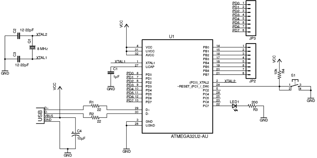
In the previous part of this microcontroller tutorial, we decided on which components to use and how to connect them. Here is the circuit diagram we ended up with:
Download the Microcontroller Tutorial
A step-by-step guide on how to make a microcontroller board you can build at home using standard hobby tools.
The ATmega32U2 microcontroller, is not in Eagle’s default library. I could have designed my own custom component, but to save time I used a library that I found here: https://github.com/civanovici/roduino/tree/master/eagle/eagleLibrary
For the USB connector, I used one from Sparkfun’s library here: https://github.com/sparkfun/SparkFun-Eagle-Libraries
Designing Our Board Layout
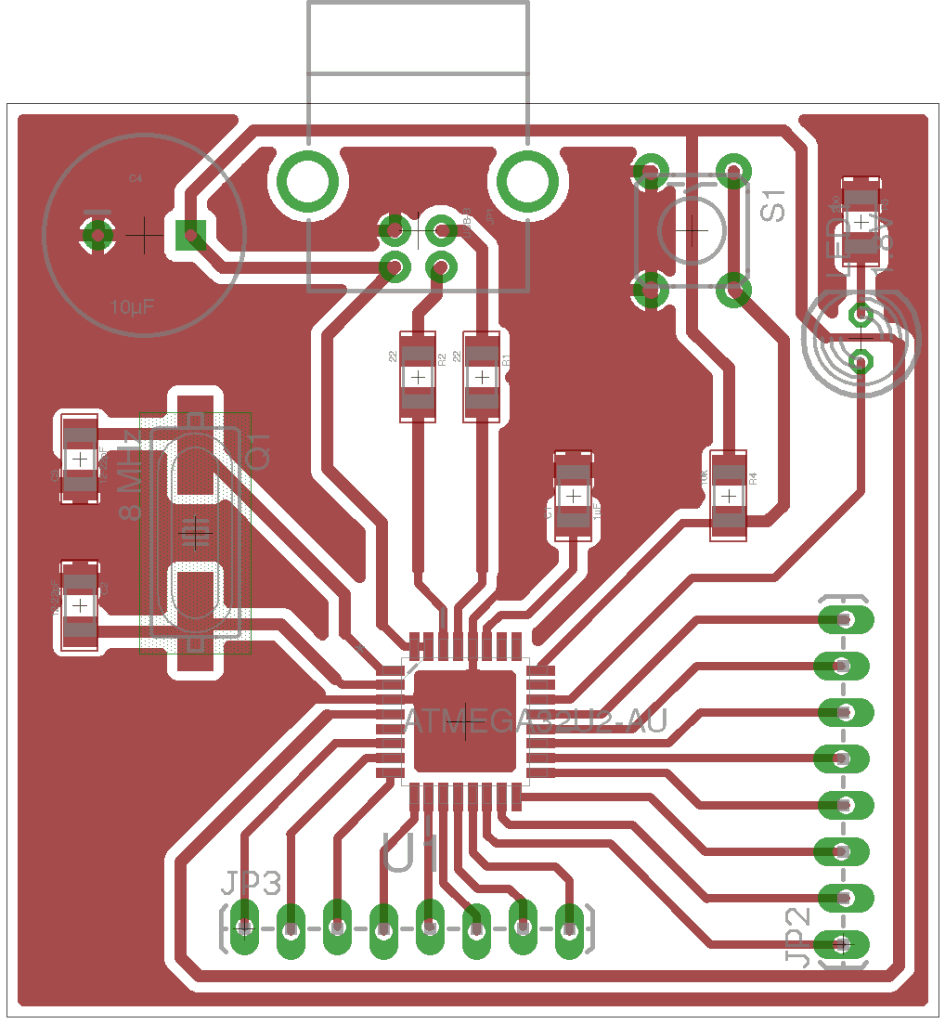
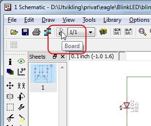 The next step is to design the board.
In Eagle, we can click on the «Board» button in the toolbar to open the design editor. If no board design exists for your schematics, you will be asked if you want to create one. Answer «Yes» to this.
I always start out by defining my board size. I know that I can get really cheap prototypes if I stick to 5cm x 5cm (1.9685 in x 1.9685 in), so I will set my board size to this.
Now it’s time to place the components onto the board and draw the connections.
In this design, I wanted to draw only on one side, so that it would be easier to mill or etch the board – just in case I wanted to do this.
You can download the finished design here: Microcontroller-tutorial-files.zip
Making the Board
There are three main ways of making a board from an Eagle design; etching, CNC milling or ordering from a prototype manufacturer. Earlier, I’ve written an overview of the three methods.
In my opinion, the easiest way is to use a PCB manufacturer. It takes a bit of time to wait for your board, but at least everything will be done properly. This does not have to be expensive. You can order 10 boards for $10 at some places. And the cheapest shipping option can be only a few dollars.
To find the best option for you, I recommend checking out pcbshopper.com that allows you to enter your board details and country, then find both price and delivery time to your country.
To see exactly how you can prepare an order of cheap PCB prototypes, check out this video:
I ended up ordering my boards from seeedstudio.com. Because I wanted to get my boards fast to continue the tutorial, I paid for the fastest shipping option. Hopefully I will get it very soon.
Getting Components
A board without components isn’t very interesting. So we need to get out hands on some components too.
There are many stores that sell components online, check out my recommendations here.
Complete Parts List
| Part | Description | Value | Package |
|---|---|---|---|
| C1 | Capacitor | 1µF | SMD 1206 |
| C2, C3 | Capacitor | 12-22pF | SMD 1206 |
| C4 | Capacitor Polarized | 10µF | Through-hole |
| JP1 | USB Connector | USB Type B Receptacle | Through-hole |
| JP2, JP3 | Header 8 pin | Through-hole | |
| LED1 | Light Emitting Diode | 1.8V | Through-hole |
| Q1 | Crystal | 8 MHz | SMD C49UP |
| R1, R2 | Resistor | 22 Ohm | SMD 1206 |
| R3 | Resistor | 200 Ohm | SMD 1206 |
| R4 | Resistor | 10k Ohm | SMD 1206 |
| S1 | Momentary Switch | Through-hole | |
| U1 | Microcontroller | ATmega32U2 | TQFP-32 |
If you can’t find a specific part, you could use findchips.com to find out which stores that have the part you are looking for.
Now we just need to sit back and wait for the boards and components to arrive.
Continue to part five where we’ll solder and program the circuit >>
More Microcontrollers Tutorials

Download the Microcontroller Tutorial
A step-by-step guide on how to make a microcontroller board you can build at home using standard hobby tools.

