In this tutorial I will teach you how to build your own microcontroller circuit. This way, you can easily add microcontrollers to your own projects. We are now at part three of this tutorial.
In part one of the microcontroller tutorial, we looked at what a microcontroller is. We saw that a microcontroller is like a small computer, and that you can use it to build amazing things like cell phones or even your own handheld game-console.
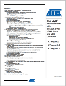
Then in part two, we looked at different types of microcontrollers, and we chose one for our purpose. We chose the ATmega32U2 because we can program it through USB and it is reasonably easy to solder at home.
In this third part of the microcontroller tutorial, we are going to design our circuit from scratch. So we need to design a schematic diagram with all the components and connections necessary to make our circuit work.
Let’s build this thing!
What Do We Need?
How do we decide which components to connect to our microcontroller?
Let’s think about it. We need power for the chip, otherwise it won’t work. And we need a USB connection, since we are going to program it through USB. And we need some physical pins where we can easily connect things to our circuit and test it.
Download the Microcontroller Tutorial
A step-by-step guide on how to make a microcontroller board you can build at home using standard hobby tools.
So, we need:
- Power
- USB Connection
- Pin Connections
The Datasheet
 To figure out exactly which components we need, and how to connect them, we look in the datasheet of the chip.
The datasheet is a comprehensive document with a lot of technical data on how the microcontroller works and how you can control different parts of it.
If you are not used to reading a datasheet, it might feel a bit overwhelming. But after looking at a few datasheets, you will sooner or later start to understand how it is laid out.
It is not necessary to read the datasheet from start to the end. You only need to read the parts that are interesting for what you want to make.
So if you want to make a timer with your microcontroller, you read the timer section. If you want to use the UART, you look up the UART section.
One thing to notice – in the datasheet of the ATmega32U2, the table of contents is placed at the end.
Power and USB
We can choose if we want the circuit to be powered by the USB cable or with an extra power cable.
To keep things simple and with less components, let’s make this a USB powered device. This means it will only work when it is connected to the USB.
So, what does this mean? Which components do we need?
To find out, let’s look in the USB-section of the datasheet, and see what we find.
USB Module Powering Options
From the table of contents at the end of the datasheet, we find a section called USB Module Powering Options at page 186. Here we can find the following figure that show us how to connect the USB section of the chip to make it powered by USB.
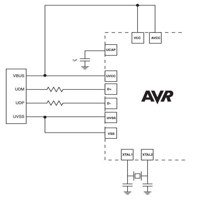
From Design guidelines on page 189 we learn that the resistors should be 22 Ohm resistors, and that it is also highly recommended to have a 10 µF capacitor on the VBUS line. So let’s add the 10µF capacitor too.
Crystal
 In the image above, we can see that there is also a crystal and two capacitors connected to the XTAL1 and XTAL2 pins. Why is this?
A microcontroller needs a clock to work. Most microcontrollers have an internal RC-oscillator that creates a clock signal. And so do the ATmega32U2.
But the thing is that the USB part of the microcontroller is not able to run from that internal clock. So to make USB work, we need an external crystal.
Exactly what kind of crystal we need, we can find at page 30 in the datasheet. Here, the capacitor values are also listed.
Pin Connections and LED
 We want to be able to connect stuff to our microcontroller circuit. So, we’ll add 16 physical pins that are connected to the I/O pins PB0-PB7 and PD0-PD7. This makes it easy to connect something to our circuit.
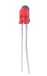
Another thing we should add, is an LED. This way, we can easily check if the circuit and our code works. To control the current through the LED, we also add a current limiting resistor in series with it.
Push-Button for Reset
It is very common to have a reset button on a microcontroller circuit. This makes it easy to reset the microcontroller without having to unplug the USB cable.
From page 47 of the datasheet we can read:
«The MCU is reset when a low level is present on the RESET pin for longer than the minimum pulse length.»
So we need to make sure the reset pin is normally pulled high, and only pull it low when the reset button is pushed.
To do this, we use something called a pull-up resistor. This is a resistor connected between the reset pin and VCC (5 volts) – which “pulls” the reset pin high.
We connect the reset button in a way so that the reset pin is connected to ground (0 volt) if the button is pushed.
A good value for this resistor is around 10k Ohm.
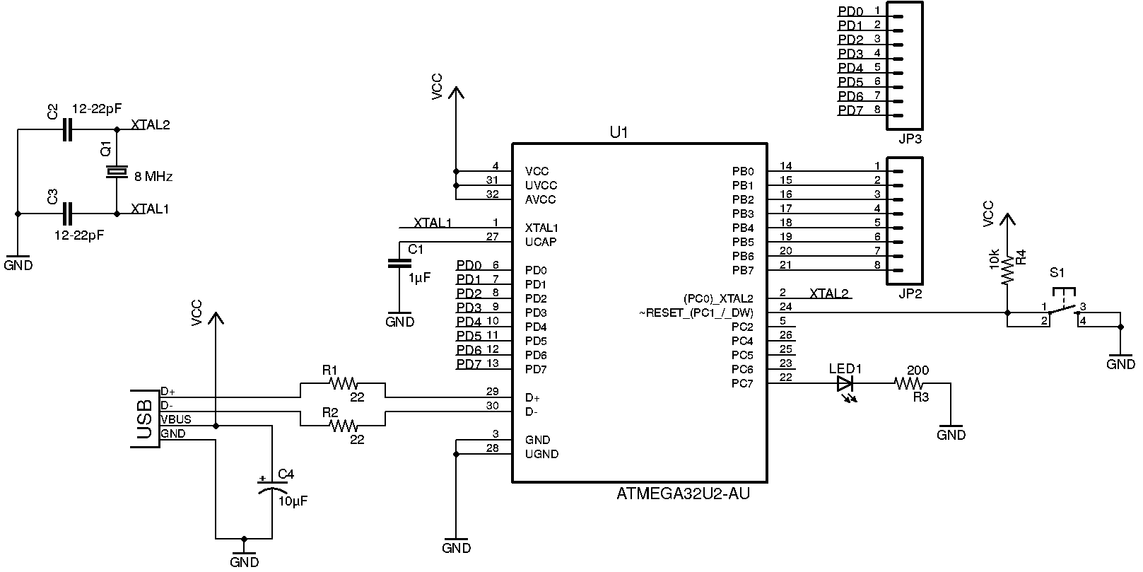
The Complete Microcontroller Circuit Diagram
If we combine all the parts that we’ve discussed above, we’ll end up with the following circuit diagram. You’ll notice that some parts seem to not be connected to the rest. But, when there is a name on a wire, it means this wire is connected to all the other wires with the same name.
Designing a Circuit Board and Getting it Made
Wow, it’s all coming together now. All we have to do now is to create a circuit board. So, that’s exactly what we’ll do in the next part of the tutorial.
Next up, we need to create this circuit and have it made.
Click here to continue to part 4 in the microcontroller tutorial >>
More Microcontrollers Tutorials
Download the Microcontroller Tutorial
A step-by-step guide on how to make a microcontroller board you can build at home using standard hobby tools.
nice tutorial,,,,is there any way we can use this component for temperature controller for an electric heater to switch ON/OFF automatically
Absolutely =) But how to do it depends on how you control the heater.
Oyvind
Thus a nice tutorial. Is there a way to use the micro-controller to control a light switching system?
Absolutely =) But also here, how to do it depends on how you control your light system.
Oyvind
Would you mind if I put a link to your website on my website?
Go ahead =)
Oyvind
Can you give us a list of all the components you are using to build this?
You can see all the components in the schematic diagram.
Maybe I’ll list them in the next part.
Oyvind
Thank you, I believe its the best thing you contributed.
How to make a simple radio control for a toy car.
I really enjoyed the tutorial, it is eye- opener to me as a beginner in this field.
Yakudala
Please can i have your book ordered in Nigeria, please to be totally and
richly blessed with it
Yes, it’s an ebook, so you can download it anywhere in the world. You can buy it here: https://www.build-electronic-circuits.com/products/getting-started-with-electronics
Cheers!
Oyvind
Hi
This is an smd micro, i’ve noticed.
How am i going to solder it to the board. Why not choose a through hole device.
Regards.
I know I’m not Oyvind but here is a link on “How to smd solder with a soldering iron”
sorry last comment did not work this is the link
I am so so sorry I’m not good with HTML this is the link you need to learn how to Smd solder with just a soldering iron
Hope it helps
How to Smd solder
I think the link Matthew is trying to post is this one: https://www.build-electronic-circuits.com/smd-soldering/
Thanks for trying Matthew :)
The reason I chose an SMD chip was because there are no through-hole AVR chips with USB. It’s really not that hard to solder. And a lot of chips come only in SMD packages, so I recommend learning it sooner than later.
Oyvind
looking forward for the next part on mcu tutorials. TY.
thanks
pls, will you tutor us on programing micro-controllers?
That will come in part 5.
Cheers!
Oyvind
nice
I cannot find the capacitor values on page 36 of the datasheet. Page 186 in the datasheet suggests a crystall of 16MHz if the power supply exceeds 4.5V. Since we have a USB connection with a 5V signal voltage, should we not use the 16MHz crystal?
I was also wondering about the maximum power of the 22 Ohm resistors that we use for the USB D+,D- connections. USB 2.0 has a maximum current of 0.5A, thus a maximum power of P=U*I=R*I*I=(22*0.5*0.5)W=5.5W. This current would never be demanded by the circuitry, but is there any hint about the current or power that the resistors has to withstand?
Hey Markus,
Great questions. I like that you are diving into it properly.
Looks like crystal and capacitor values are on page 30 now.
Page 186 suggest a crystal of MAX 16 MHz for 5V. But less is also ok.
About the max power of the 22 ohm resistors: The resistors are on the data lines. The 0.5 A is the max power from the VBUS line. I’m not sure how much power the resistors need to be able to handle, but since I’ve never seen it specified I assume 1/4W resistors are good enough.
Cheers!
Oyvind
does this micro-controller can be programmed using keil or only AURDINO
I’m not familiar with Keith. Arduino does not work without changing the bootloader I think…
Is it necessary to memorize what VCC, UVCC, AVCC etc. and to know it’s meaning? it makes me a lit’l confusion about the diagram.
These power different parts of the chip. You can find information about these pins in the datasheet. But often, they can all be connected to one power source.
Best,
Oyvind
Is it possible for circuit to be powered by an external power source such as a button battery as well as be programmable through USB?
If the circuit uses very little energy, then it’s possible. For this one, I doubt it.
As soon as you(admin) reached at the 3rd part of the tutorial, where you, started talking about the usage of resistors and capacitors, I kind of started getting a hunch of complexity, because I am not good at basics (why, where, how and what type of resistors and capacitors do we use) in multiple applications/circuits.
If you clear my doubt that I will be very helpful for me to pursue my career.
Regards
Dhaval Taneja
Here’s a place to start:
https://www.build-electronic-circuits.com/basic-electronic-components
Best,
Oyvind
Great tutorial, I plan on starting it soon.. but my question is, what kind of USB should I use? (Micro, Mini, Type A/B, etc)? Or doesn’t it matter?
You should use Type B as that is the type used on non-host devices. But it doesn’t matter if you choose mini or micro.