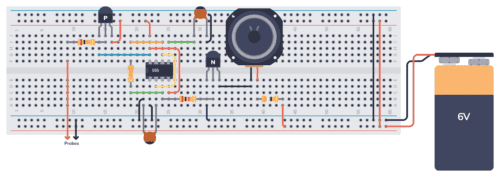
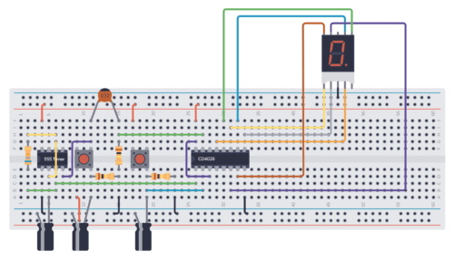
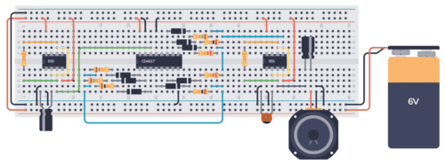
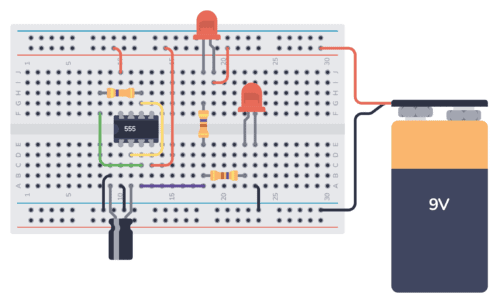
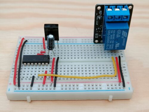
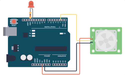
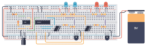
Are you starting out in electronics? Then these simple electronic circuits will make it easy for you to start building electronic circuits.
The first time you want to build a circuit, it can be a little bit daunting. “What if my schematic is wrong? What if I did a mistake on the PCB design? What if my Gerber files were not created correctly?”
Well, I decided to make it easy for you. For each of the three simple circuits I provide a description, a schematic (Eagle), PCB design (Eagle) and even Gerber files that you can download.
This way you can choose if you want to start from scratch, start from schematics, start from finished PCB design or just download the Gerber files and get the circuit built.
“Hello World” Circuit
The first of the simple electronic circuits is this little fella. It has a battery holder, a couple of resistors and six light emitting diodes (LEDs). The reason I call it “Hello World” is because when you turn the power on, the LEDs light up the words “Hello World” written on the PCB layout I have created.
There isn’t much magic going on here, just a battery providing electrical current to some LEDs when you switch it on. But it is a good electronic circuit to start with for the sake of practice. Maybe you can hang it at your desk to remind you of your first professionally built circuit =)
Download schematics, PCB and Gerber files: helloworld.zip
Note: The “Hello World!” text was designed to fit the 5cm x 5cm board perfectly, but the PCB manufacturers doesn’t always support the text size you have chosen. Look at the picture below. On the PCB I ordered from Seeed Studio the text was made larger and thereby it did not fit on the board.
Transistor Blink LED Circuit
This is the solid-state version (no moving parts) of the blinking LED circuit. I think it is the coolest of these simple electronic circuits.
The size of the capacitors C1 and C2 dictates how fast the two LEDs will blink. The resistors R1 and R4 limits the current for the LEDs while R2 and R3 limits the current for the transistor. The BC548 transistor is a NPN transistor which is very, very common and you should be able to find it everywhere they sell electronics parts.
Watch the following video to see it in action:
[youtube http://www.youtube.com/watch?v=s4-uB28VCMo&w=640&h=480]
To understand how it works, you need to understand how transistors work. The circuit is called an “astable multivibrator”. It is a hard circuit to understand, but here is a really good resource for understanding it: http://www.falstad.com/circuit/e-multivib-a.html
A common mistake when soldering this electronic circuit is to swap R1/R4 with R2/R3. So if you solder this and it doesn’t work, check that you have the resistors in their correct place.
Download schematics, PCB and Gerber files: led-blink-transistor.zip
Relay Blink LED Circuit
When I started learning about electronics I had a hard time understanding how to blink a light. My father explained it to me using a relay, a capacitor and a small light bulb.
This circuit is much easier to understand than the blinking LED circuit using transistors.
The relay is powered through its own NC (Normally Closed) switch. The same is the LED. So when the circuit is powered up, the LED will lit up and the capacitor starts charging. When the voltage over the capacitor is high enough, the relay pulls the switch into its NO (Normally Open) position. This means that the capacitor starts discharging and the LED is turned OFF. The voltage starts dropping on the relay coil and when it is low enough, the switch is released into its NC state. And the process is repeated.
Download schematics, PCB and Gerber files: led-blink-relay.zip
Note: Because I made a mistake on the first version, I have not tested the attached files. But I have made a breadboard version of it that you can see below:
[youtube http://www.youtube.com/watch?v=Dqjp5Ns4mkQ&w=640&h=480]
Wanna Build More Than Just Simple Electronic Circuits?
Even though I recommend starting from scratch when you build one of these simple electronic circuits, I understand that sometimes you want to be safe. So feel free to download the Gerber files and just get them produced instead if you feel like it.
prathmesh parab says
nice site
danimal says
in your blog post, How I Learned The Flashing Light Circuit, this is exactly where I’m looking to start with electronics. my question is in your story , you have no mention of volts and how do you know if your components will all work together and if they didn’t, which component is giving you the problem.
That is my issue right now. I’m sure by trial and error i can get the circuit to work, but if i want to have a bigger light, how to know what parts need to change?
admin says
Hey,
When I built that circuit, I had no idea about volts or if components fitted together. I did some trial and error, and with the help of my dad I made it work.
To understand more about what’s going on, you need to learn a bit more about vopltage, current and resistance, and how to basic components work.
Here’s one place to start: https://www.build-electronic-circuits.com/products/ebook-2nd-edition
vic says
hey,i am in Nigeria and we don’t have electronic shops selling these components. this is my major problem. pls help me.
admin says
Hi, you can try online shops like http://www.taydaelectronics.com
Best,
Oyvind
Maywar says
Can i use c9014
Harry says
Dear Admin,
I really liked your blog and i have gathered a lot of knowledge from here, i want to make a ultrasonic humidifier using piezo electric disc, that has a frequency of either 2.4 or 1.7 mega hertz, can you please help me, in designing a circuit that can generate the same frequency.
Thanks and regards,
Harry
Montel says
There are electronics shops in Nigeria that sell these components, I know of places in Lagos and Osun state
Vita says
Hello Admin,
I have a question to the Relay Blink LED Circuit. The circuit in “explained it to me” link drawn by hand is clear to me and I understand it. But I have a problem with original circuit where it seems to me that the capacitor is in parallel with relay. Also it looks like to me that relay “switching crossroad” is not in series with LED. Because of that, I would think, that LED could be ON all the time, because “switching crossroad” does not disrupt flow of the current through LED, no matter what position the relay is in. Do you undertand my problem? Could you please explain it to me or give me a hint where I could undertand it better?
Thanks
Vita