A continuity tester is an indispensable tool when working with electronic circuits. This 555 Timer Continuity Tester uses a 555 Timer IC to generate an audible tone when a continuous path (continuity) is detected between the two probes.
This tester will work with resistances up to 200 kΩ. Additionally, it has an automatic turn-off feature to conserve battery life when the tester is not in use.
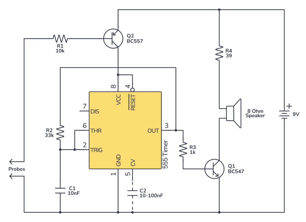
The Circuit
You can build this circuit using a 555 timer, a speaker, an NPN transistor, a PNP transistor, a capacitor, and some resistors.
Parts List
- 9V Battery
- 555 Timer IC
- BC547 NPN Transistor (Q1)
- BC557 PNP Transistor (Q2)
- 8 Ohm Speaker
- Resistor, 10kΩ (R1)
- Resistor, 33kΩ (R2)
- Resistor, 1kΩ (R3)
- Resistor, 39Ω (R4)
- Capacitor, 10nF (C1)
- Capacitor, 10-100nF (C2) – Optional
How it Works
In this circuit, the 555 is configured in astable mode to generate a continuous tone when the circuit is closed. A PNP transistor (Q2) is used to disable the circuit when the probes are not in contact. This setup saves battery power by automatically turning off the circuit when not in use.
When the probes do not detect continuity, Q2 is off, and so is the 555 timer as its Reset pin (pin 4) is tied to Q2’s collector. Upon detecting continuity, a small current flows through R2 and between the probes, turning on Q2, which allows the 555 timer to oscillate and generate a tone through the speaker.
R1 and C1 set up the frequency for the audible tone. Tweak these values if you want a different tone.
The transistor Q1 is set up to power the speaker directly from the battery instead of pulling current out of the 555 timer.
Building The Continuity Tester on a Breadboard
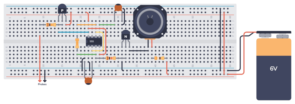
Start by placing the 555 Timer with the capacitor (C1) and the resistors (R2 and R3) on the breadboard and wire it up according to the schematic diagram.
Build Something Practical This Evening
Download this tutorial that shows you step by step how to build an old-school USB charger for your mobile.
Connect the transistor (Q1), the speaker, and the resistor (R4) and add all necessary connections.
Then finally, attach the transistors Q2 and R1. Make sure you use the PNP transistor and orient it the correct way. The probes can be attached to the board using jumper wires.
After ensuring all connections are correct, connect the battery to the circuit.
Now touch the probes together; you should hear a tone from the speaker, indicating continuity.
Troubleshooting Tips
- If there’s no tone when there should be continuity, check if Q2’s base-emitter junction is forward-biased (i.e., a small voltage from the probes through R2) when the probes are touched together.
- Make sure all components are correctly oriented, especially the IC and the transistors.
- Ensure that all components are making proper contact with the breadboard and there are no loose connections.
- Verify that the speaker is functioning and properly connected; if it’s not, you will not hear any tone.
More 555 Timer Tutorials

Build Something Useful This Evening
This gadget lets you use any IR remote-control to control your lamp, garden lights, heater oven, garage door, or anything else.
Voor een heel luide geluid te maken ,wat moet ik dan voor veranderen
Ik ben maar een gewone leek daarin ,maar wel erg geinteresseerd en heel boeiend om daarover te leren.
Mvg
Frank
I love you.
The breadboard shows two capacitors, yet the parts list and circuit diagram only shows one.
You’re right! It’s really not necessary to use it according to most datasheets. It just gives better stability. But I’ve heard stories of people who’s circuit does not work without it, so there might be some version of the chip that needs it.
Anyway, I updated the schematic to match.
Hi, i have two remarks.
I did not build it yet but shouldn’t the discharge-pen be connected? Now it is just floating and an “astable” set up should discharge the capacitor at 2/3.
Also, the schematic does not connect Vcc to the plus-terminal while the breadboard does.
The output-pen3 is connected to C1 and I am not familiar with this setup. I am wondering how the block-wafe for the speaker is generated.
Now I am curious, I will build this thing soon.
The Astable 555 in this configuration is using one resistor instead of two by using pin 3 for charge and discharge of capacitor instead of using discharge pin. This configuration works well if pin3 is not connected to a high load which will disrupt the charge cycle of the capacitor. This justify the use of NPN transistor where base will draw very small current.