This is a fun project to build – a 555 Timer music box! It’s based on two 555 timers, one that sets the tempo of the music, and one that creates the different tones. The sequence of which tones to play is managed by a decade counter IC and some resistors.
The Circuit
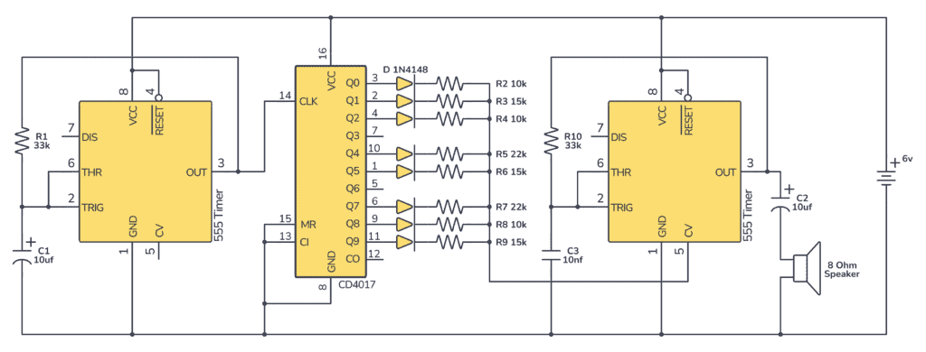
You can build this project using two 555 timers (or one 556 timer), a CD4017 IC, some diodes, resistors, capacitors, and a speaker.
Parts List
- Resistors:
- R1: 33k ohm
- R2: 10k ohm
- R3: 15k ohm
- R4: 10k ohm
- R5: 22k ohm
- R6: 15k ohm
- R7: 22k ohm
- R8: 10k ohm
- R9: 15k ohm
- R10: 33k ohm
- Capacitors:
- C1: 10 µF
- C2: 10 µF
- C3: 10 nF
- Integrated Circuits:
- 555 Timer IC
- CD4017 Decade Counter IC
- Diode:
- D1-D8: 1N4148 (or other signal diode)
- Speaker:
- 8 Ohm Speaker
How It Works
This 555 Timer Music Box is a project designed to create 10 different musical tones. It uses two main components: a 555 timer and a 4017 decade counter.
The two 555 timers are set up in a way that they produce a square wave – basically an on-off pattern. The first one with a set frequency to control the tempo of the music, and the second one with a variable frequency that goes out to a speaker and creates the tone you hear.
The frequency or pitch of the tone of the second 555 timer is determined by the resistor value of the CD4017 output that is currently active.
The 4017 decade counter is a chip that counts the pulses from the first 555 timer and turns on one of its 10 output pins (Q0 to Q9). Each output pin is connected to a different resistor (R2 to R9 and R10). These resistors are connected to the second 555 timer, specifically to its control voltage pin (pin 5). Changing the voltage at pin 5 changes the frequency of the 555 timer’s output, thus altering the pitch of the sound produced.
When the 4017 counts, it turns on each of its outputs one after the other. Each time an output goes high, it changes the voltage at pin 5 of the 555 timer, which in turn changes the pitch of the tone. This way, the circuit can produce 10 different tones.
The “unused outputs” of the 4017 (those not connected to resistors) will produce a tone that is the same as the 555’s base tone — the tone you’d get if you didn’t alter the control voltage at pin 5.

Get the 555 Timer Cheatsheet
A super helpful reference that makes it easy to design circuits, so that you can build oscillators, timer circuits, and more in no time.
So, in essence, this circuit is a simple synthesizer that can cycle through 10 different pitches to create a tiny piece of music sequence, depending on the specific resistor values chosen.
Build The Circuit
Here’s how you can connect this circuit on a breadboard:
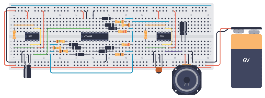
There are a lot of connections that need to be right in order for the 555 Timer Music Box to work. I recommend building and testing the circuit in stages.
First, build the first 555 timer circuit, and check that it gives a reasonable beat to set the tempo. You can check by connecting an LED with a resistor to its output pin and look at how fast it blinks.
Next, connect the 4017 circuit and use a multimeter to check that its outputs go high one by one.
Finally, connect the second 555 timer circuit, without connecting it with the 4017 circuit via pin 5. It should give out a steady sound. Then, connect it with the 4017 circuit via pin 5 and you should hear the tones change in the tempo set by the first 555 timer.
More 555 Timer Tutorials
Get the 555 Timer Cheatsheet
A super helpful reference that makes it easy to design circuits, so that you can build oscillators, timer circuits, and more in no time.
I build the circuit but it looks like something is wrong, no sound is coming out, can a 9V battery be used also or only 6V. if you have any tips to give me I would really appreciate it.
Yes, you can use 9V.
Try disconnecting pin 5 of the second 555 timer and leaving it unconnected. This should give you a steady beep if the second 555 timer is working correctly. If not beep, the issue is with the circuit for the second 555 timer, so that’s where you should start looking for issues.
Hello. I have questions:
– If I reduce that to 8 steps, what should I do with pins 9 and 10 so that it doesnt just “play’ two empty steps? Connect them to ground?
– I guess I could replace any resistor by potentiometers?
-Can I mute/unmute steps, and if so, how? By inserting a switch vetween CD4017 output and the resistor+LED ?
Thanks.
Hi Paul,
If you want to reduce to 8 steps, take output 9 and connect it to the reset pin. Reset is currently connected to ground, so it must be disconnected and connected only to putput 9. And yes, you can use a potentiometer instead and mute/unmute steps with switches like you suggest.
In the breadboard image you have pin 13 and 15 wired to the red rail with the black wire. They should be wired to the blue rail(GND). I was getting sound with both wired to Vin but it was all the same tone/pitch as it cycled through. After changing the pin 13 and 15 to GND, It worked perfectly.
Why are the diodes needed in this?
To avoid that one output being high will affect the other outputs that should be low. With the diode, current can only flow from the output, not back into it.
Hi ! I’m trying to recreate this circuit for my school project and it is not working … any help or advice ?
Hello, I am trying to find the duty cycle for the circuit. How would I go about doing this? Would I need to find the duty cycle of each resistor individually, or is there a way to find the duty cycle using the third IC? Thank you!