Here is a nifty little circuit that’s designed to make sure nobody messes with your TV settings while you are watching your favorite show – a 555 timer TV remote jammer!
This sneaky device sends out an invisible signal at a frequency that the TV thinks is coming from a remote control. But instead of changing the channel, it just fills the air with noise that the TV can’t understand.
The Circuit
To build this circuit, you’ll need a 555 timer, a potentiometer, a couple of diodes, a transistor, some resistors, capacitors, and an IR LED.
Parts List
- 555 Timer IC
- IR LED
- Q1: Transistor NPN
- C1: Capacitor 10 nF
- R1: Potentiometer 10 kΩ
- R2: Resistor 1 kΩ
- R3: Resistor 470 Ω
- R4: Resistor 56 Ω
- D1, D2: Diode 1N4148
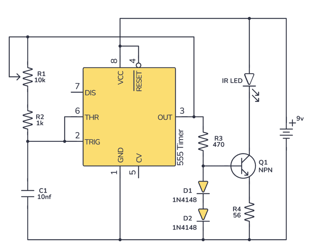
How It Works
This circuit is all about that 38kHz signal—it’s the sweet spot that most TV remotes use to chat with your television. The 555 timer sets up the frequency, and you can use the potentiometer to fine-tune it.
The IR LED will blink with that frequency to send out the IR signal. IR stands for infrared, which is a type of light that’s just out of sight for our eyes, but TV sensors can pick it up like a dog hears a whistle.
The transistor, the two diodes, and the 56 Ω resistor (R4) make up a constant current source to make sure the IR LED gets around 12 mA of current.
Build The Circuit
You can build a prototype of this circuit to test it out on a breadboard:
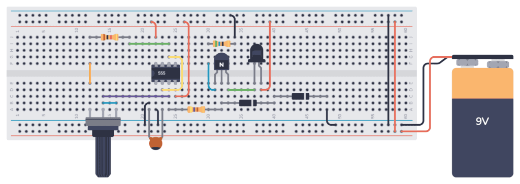
Once everything is connected, you can power the 555 Timer TV Remote Jammer by connecting a 9V battery. The IR LED should start emitting the 38kHz signal, effectively jamming nearby TV remotes.

Get the 555 Timer Cheatsheet
A super helpful reference that makes it easy to design circuits, so that you can build oscillators, timer circuits, and more in no time.
Build this circuit, point it at your TV, and it’s like you put up an invisible ‘Do Not Disturb’ sign for any other remotes.
Remember, it’s important to follow the schematic diagram accurately to ensure the circuit works correctly.
More 555 Timer Tutorials
Get the 555 Timer Cheatsheet
A super helpful reference that makes it easy to design circuits, so that you can build oscillators, timer circuits, and more in no time.
I love the idea of this circuit but be warned – a lot of new TV & set-top-box remote controls now use Bluetooth instead of IR, so check which you have before you start messing with its settings.
Hi, I don’t understand why we need to use diodes. What are they changing, is it to reduce the voltage?
They set up a constant voltage for the base of the transistor of about 1.4V. Which means the 56 ohm resistor gets about 0.7V across and the current becomes predictable (0.7V/56 ohms = 12.5mA). Since the current is approximately the same in the collector and emitter, it means the IR LED also gets 12.5 mA.
So with the diodes, we’re creating a constant current source for the IR LED.
Thats so cool im doing this some what the same but using a microcontroller that uses 2 tsal6200 100ma the microcontroller so fast to each frequency and nec garble through one and frequency on the other insuring nothing gets through to the tv just waiting on the ir right now and voltage booster for the power i need and since its on the rp2040 connect I can use bluetooth as well the code is finshed just waiting for the parts. But your circuit will be the base of another project pretty much doing something like the microcontroller having 3 555 timers set to different frequency not all tvs use 38khz so have 3 or 4 frequency using a cd4017 and a multiplexer ic to switch through each frequency making it a cool circuit only in my head now but I have the 4000 series on it way with the others thanks will try your circuit and really if you added a potentiometer you could find tune it until It blocks the tv your attacking
if we bias the transistor with the diodes to supply a constant 12ma, then the led isn’t blinking, which defeats the purpose of the 555 timer, doesn’t it?