This year’s Halloween project is a useless machine built with 555 timers. It’s a coffin with a switch. When you flip it off, a dark force rises from the coffin and flips it back on. This project uses two 555 timers to control the position of a servo motor, which was a fun challenge in itself.
Check out the video below to see the result:
Controlling a Servo with 555 Timers
The idea for this project came after we published the simple 555 PWM circuit that controls a DC motor using a PWM signal created by a 555 Timer. I started thinking about the idea of controlling a servo instead.
After some experimentation, I realized that the frequency changed too much when I changed the duty cycle. So my servo would only move at random times.
I decided to use two 555 timers instead: one in astable mode to set the frequency to a steady 50 Hz. And one in monostable mode that would set the duty cycle. With this setup, I was able to control the servo without any issues.
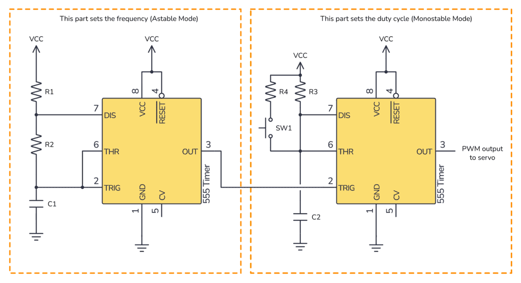
The value of the resistors R3 and the capacitor C2 sets the standard duty cycle. This position is when the arm is hidden.
When you push the pushbutton SW1, R4 is connected in parallel with R3 which reduces the duty cycle and moves the servo to its other position. This is the position that should make the arm flip off the toggle switch.
I used a pushbutton for this experiment. But in the useless machine setup, SW1 would be a toggle switch.

Build Something Practical This Evening
Download this tutorial that shows you step by step how to build an old-school USB charger for your mobile.
Adding a Delayed “button push”
The switching between the two positions happened a bit too fast. I was barely able to remove my finger before the servo arm moved into position to flip the switch back off. So I needed a way to delay things before the arm switched positions.
I tried a few different things before I ended up with the following: A pMOS to replace SW1. And a capacitor and resistor to add a delay from the toggle switch is flipped to the pMOS turns on.
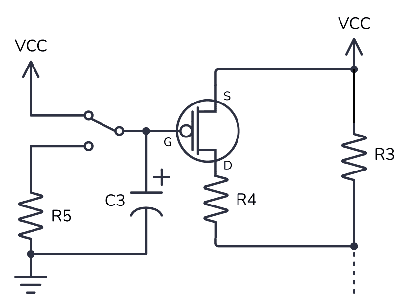
Basically, what this circuit does is that it places R4 in parallel with R3, just like SW1 did before. But it does so after a short delay of a couple of seconds. The values of C3 and R5 sets the delay time.
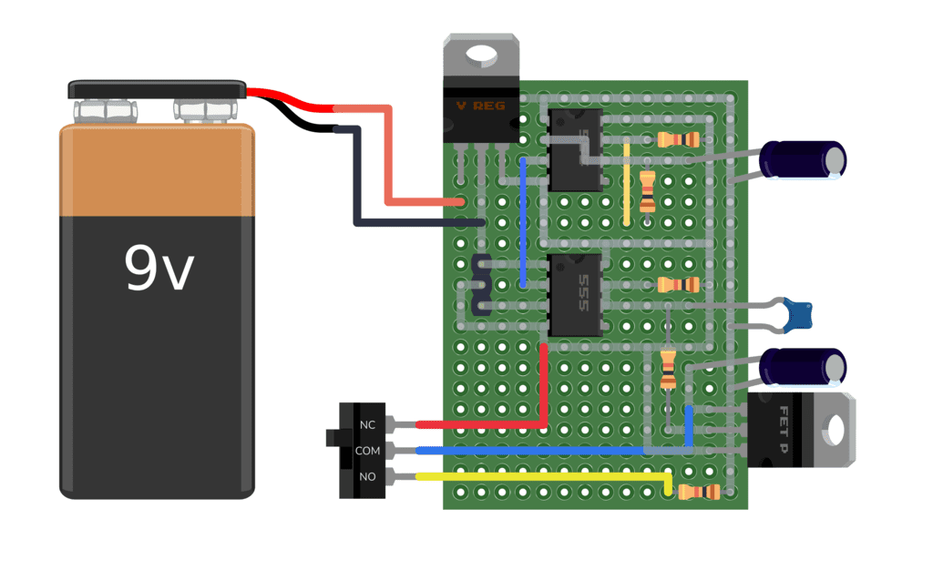
The Final Circuit
The delay circuit worked perfectly. And below you can see the full schematic for this project:
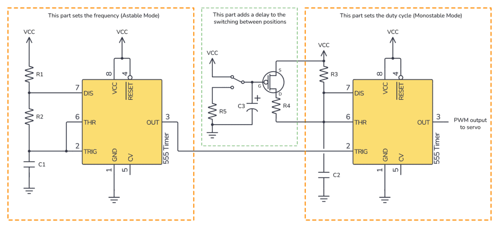
The only part of the circuit that is not shown above is a 7805 voltage regulator that converts my 9V battery to 5V, which was the VCC voltage I used to make everything compatible with my servo.
Components Needed
- Servo motor (I used SG90)
- Toggle switch
- Box to put everything into
- 2 x 555 Timer
- 1 x pMOS transistor
- 5 x Resistors (See below for values)
- 3 x Capacitors (See below for values)
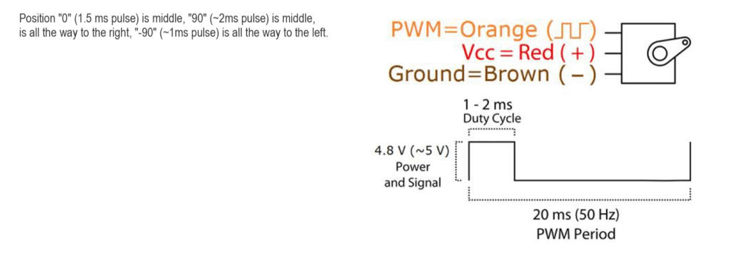
To choose values for the first 555 timer, you need to start with the specs of your servo. My servo, the SG90, needs a frequency of 50 Hz. And you control it’s position by adjusting the time on between 1 and 2 ms.
Choosing values for the first 555 timer
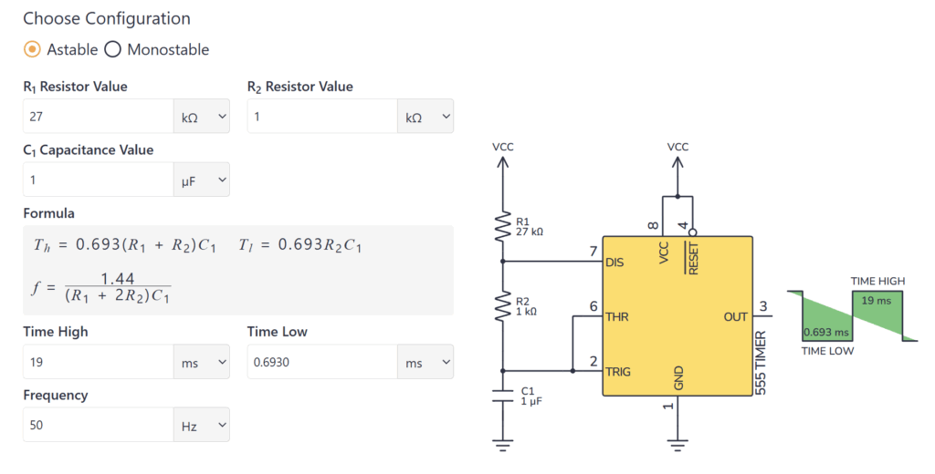
Use this 555 calculator in astable mode and try different values until you find the frequency you want.
But there is one important thing here: The output from second 555 timer will never be shorter than the input trigger pulse. So if you want a 1 ms pulse out, you have to make sure that the trigger output (the low pulse) from the first 555 timer is shorter than 1 ms.
Here’s one set of values that will give you a frequency of 50 Hz and a low pulse length of ~0.7 ms:
R1: 27 kΩ
R2: 1 kΩ
C1: 1 µF
Choosing values for the second 555 timer
To choose values for the second 555 timer, use the 555 calculator in monostable mode and try different values until you find the resistance you need for the two different servo positions.
For example, using a 1µF capacitor and a 1 kΩ resistor, will give a 1.1 ms pulse. Switching to a 1.8 kΩ resistor will give you a 2 ms pulse.
Use the highest resistance value for R3 (1.8 kΩ using the previous values). R4 will be in parallel with R3, so you need to figure out what R4 needs to be in order to get the lowest resistance value (1 kΩ). This calculator might be of help.
The following values will give you the two pulses of 1 ms and 2 ms:
R3: 1.8 kΩ
R4: 2.2 kΩ
C2: 1 µF
If you’re using the SG90 servo, then 1 ms will move the servo to one extreme, and 2 ms to the other extreme. You might not want the servo to go all the way to both sides, so this is where your job of tweaking the values comes into play ;)
More Circuits & Projects Tutorials
Build Something Practical This Evening
Download this tutorial that shows you step by step how to build an old-school USB charger for your mobile.

