A potentiometer is an adjustable resistor with three pins. The fact that it has three pins instead of two was confusing to me when I was starting to learn electronics. But as soon as I saw the inside of it, it all made sense.
In this guide, I’ll show you what the potentiometer looks like on the inside, the different potentiometer types, and examples of how to wire it up for different circuits.
What Is A Potentiometer?
Potentiometers are adjustable resistors used in circuits for many things, such as to control the volume of an amplifier, control the brightness of a light, and much more.
It is like the resistor. But while the resistance value of a resistor stays the same, you can adjust the resistance value of a potentiometer.
A potentiometer has three pins and the schematic symbol looks like this:

But you don’t need to use all three pins if you don’t need them. It’s totally fine to use just two pins.
Once you learn how it’s made, you’ll quickly understand how to do that. But you can also jump right to the wiring examples at the end if you just want to see some examples of how to connect a potentiometer.
How Potentiometers Are Made
A potentiometer is made of a strip of resistive material, usually a carbon mixture. Plus a wiper that can be adjusted and placed somewhere on that strip.

Get Our Basic Electronic Components Guide
Learn how the basic electronic components work so that circuit diagrams will start making sense to you.
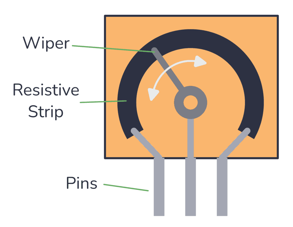
Each far side of the strip is connected to a pin. And the middle pin is connected to the wiper.
The wiper touches the strip somewhere between the two ends. The position of the wiper determines the resistance between the wiper and the side pins. You can move the point where the wiper connects to the carbon strip by turning the shaft of the potentiometer.

When you move the wiper to the left side, the resistance between the middle pin and the left pin decreases. And the resistance between the middle pin and the right pin increases.
Move the wiper to the right, and the opposite happens.
When you buy a potentiometer, you have to choose a value. For example 100k. This is the value you get if you measure the resistance between the two end pins. And it’s the largest resistance value you can get from the potentiometer.
Potentiometer Types
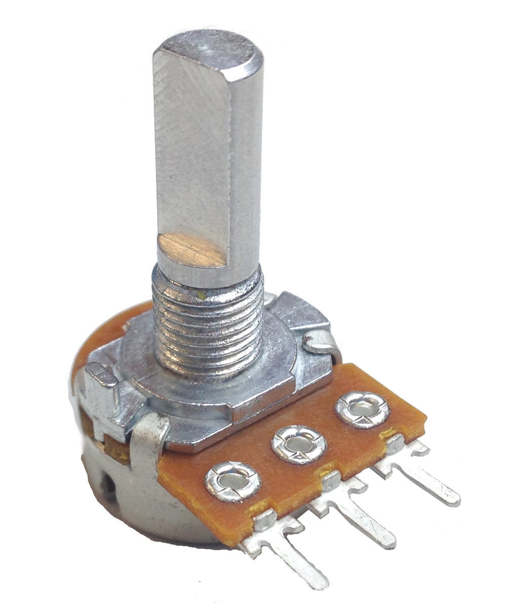
Rotary Potentiometer
This is the most common type. It has a shaft that can be turned, and the resistance changes as you turn the shaft. It’s often used for adjusting the volume on guitar pedals, audio amplifiers, and other audio equipment.
This type of potentiometer can be found with values that change linearly or exponentially. The exponential version of the pot is usually used for adjusting audio volume.
Dual or Stereo Potentiometer
This is the same as the rotary potentiometer, just that it contains two potentiometers operated by a single shaft. This makes it possible to control two channels at the same time, such as the left and right channels of a stereo system.
Linear or Slide Potentiometer
A slide (or linear) potentiometer looks like a slider and you change the resistance as you move a slider or wiper in a straight line.
This type of potentiometer is commonly found in audio mixing consoles as faders.
Trimmer or Trimpot
A trimmer potentiometer, also called a “trimpot”, is small and is often used for occasional adjustments, such as during setup or calibration. It’s typically mounted on PCBs and adjusted using a small screwdriver.

Digital Potentiometer
A digital potentiometer is a chip where you can adjust the position of the wiper through digital signals, such as SPI or I2C.
This can be very useful if you want to be able to change resistance on-the-fly from an Arduino or other microcontroller. For example to adjust LED brightness.

Potentiometer Wiring Examples
The way to wire up a potentiometer depends on how you’re planning to use it.
Usually, the middle pin is the wiper. And the resistance between the wiper and the right pin will decrease as you turn the shaft (or move the slider) to the right. If you move it to the left, the resistance between the left pin and the wiper will decrease.
Sometimes, it makes sense to use all three pins. Other times, you only want to use two. Let’s look at some examples.
Wiring Example #1: Potentiometer as a Simple Variable Resistor
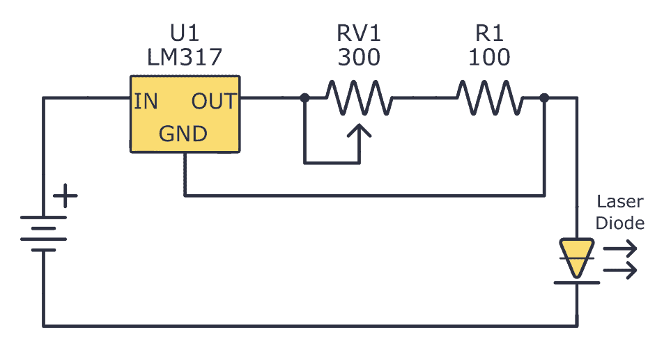
If you need a simple resistor that you can change the resistance of, you only need two pins: the middle pin and one of the side pins.
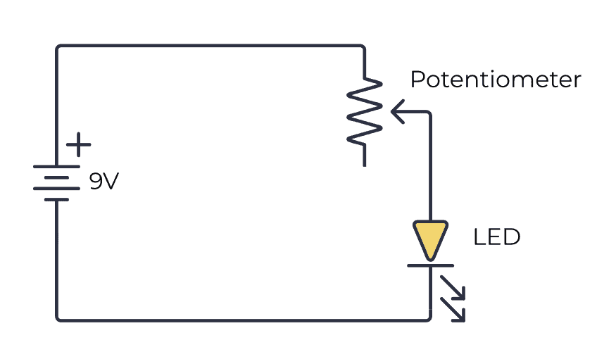
The above image shows a simple circuit to dim a Light-Emitting Diode (LED). In a real circuit, you might want to add an extra resistor in series to make sure you don’t destroy the LED even if you adjust all the way to one side so that the resistance becomes zero.
Turn the shaft in one direction and the resistance increases so that the LED becomes dimmer. Turn it in the other direction and the resistance decreases and the LED becomes brighter.
Wiring Example #2: Connecting the Third Pin to the Middle
Sometimes you’ll see circuit diagrams where the middle and bottom pins are connected to the same point. Why?
This way of connecting is actually equal to using only two pins. Connecting the third pin to the middle pin does not affect the resistance at all.
So why do it?
Some people prefer it this way because they feel it’s a bit messy having an unconnected pin, so they connect it like this. It also makes the circuit diagram a little bit nicer-looking I think.
Wiring Example #3: Potentiometer as Volume Control
This example uses all three pins of the potentiometer to create a simple way of adjusting the volume of an audio amplifier.

By connecting it like this, you’ll get a voltage divider that decreases the voltage of the input signal. The more you turn the shaft, the more you decrease the volume.
This wiring is very common in audio equipment.
More Electronic Components Tutorials
Get Our Basic Electronic Components Guide
Learn how the basic electronic components work so that circuit diagrams will start making sense to you.