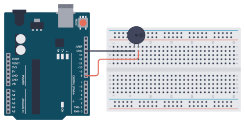
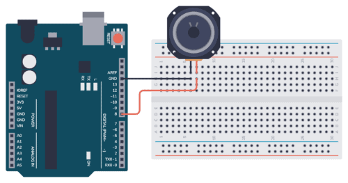
Voltage Divider Tutorial For Beginners

A voltage divider is a circuit that creates a smaller voltage from an input voltage by using two resistors. You’ll see it in both simple and advanced circuits all the time. Here’s the basic setup:

The basic voltage divider circuit

It is useful for example for reading sensors like thermistors and photoresistors since it converts an unknown resistance into a voltage. Or to reduce the volume of an audio signal via a potentiometer.

You can find the output voltage by inserting the resistor values and the input voltage into the following formula:

V_{OUT} = \frac{R2}{R1+R2} \cdot V_{IN}

Or you can use the calculator a little bit further down on this page.

Once you know how it works, it’s much easier to see how circuits work. And it will let you calculate voltages at many different points in a circuit – which is often needed to understand it.

NOT Gate (Inverter) – Logic Gates Tutorial

A NOT gate (or inverter) is a logic gate where the output is the opposite of the input. So you can say that the output is NOT the same as the input. It’s often called an inverter since it inverts the input. The schematic symbol for an inverter is like a buffer, just with a

NOR Gate – Logic Gates Tutorial

A NOR gate is a logic gate where the output goes HIGH (or “1”) only if all its inputs are LOW (or “0”). The schematic symbol for a NOR gate is like the OR gate, just with a circle at the output to indicate that it’s an inverted version of OR. “NOR” stands for NOT-OR

OR Gate – Logic Gates Tutorial

An OR gate is a logic gate where the output goes HIGH (or “1”) if any of its inputs are HIGH. So if A OR B is HIGH, the output Q also becomes HIGH. If A or B is true, then Q is true Truth Table OR gates can have more than two inputs. But

NAND Gate – Logic Gates Tutorial

A NAND gate is a logic gate where the output goes LOW (or “0”) only if all its inputs are HIGH (or “1”). The schematic symbol for a NAND gate is like the AND gate, just with a circle at the output to indicate that it’s an inverted version of AND. “NAND” stands for NOT-AND

AND Gate – Logic Gates Tutorial

An AND gate is a logic gate where the output goes HIGH (or “1”) only if all its inputs are HIGH. So if the inputs A AND B are HIGH, the output Q will also be HIGH. If A and B are true, then Q is true Truth Table AND gates can have more than

XOR Gate – Logic Gates Tutorial

The XOR gate is a logic gate where the output goes HIGH (or “1”) if one – and only one – of its inputs are HIGH. XOR stands for Exclusive-OR. Check out its symbol and truth table below. If A and B are different from each other, then Q is true Truth Table XOR gates

XNOR Gate – Logic Gates Tutorial

An XNOR gate is a logic gate where the output goes HIGH (or “1”) only if both its inputs are equal. So if the inputs A and B are both HIGH or both LOW, the output Q will be HIGH. If A and B are the same, then Q is true Truth Table XNOR gates

Logic Gates: The Beginner’s Guide to How They Work

Logic gates are the basic building blocks of digital electronics. These are the components that we use for “doing stuff” with the 1s and 0s. You can combine them to create other building blocks like latches, flip-flops, adders, shift registers, and more. The basic logic gates are AND, NAND, OR, NOR, XOR, XNOR, and NOT.

Ohms Law – The Complete Beginner’s Guide

Ohms law is a simple formula that makes it easy to calculate voltage, current, and resistance. You can use it to find what resistor value you need for an LED, how much power your circuit uses, and much more. It’s one of the few formulas in electronics that you’ll use on a regular basis.

Cap Half Full #7 – Opamp basics and the 4000 series IC

In this episode, we talk about operational amplifiers (opamps) and the 4000 series IC that Øyvind has been writing a series of posts on. We also accidentally came across a funny error on Arrow’s website 😅.

Repairing Electronics: Electronic Candle

When visiting my parents for Christmas, my dad showed me three electronic candles that did not work anymore. He told me he had changed batteries and showed me that they did not show any signs of life.

I tried to get them to work as well, but no luck.

It sounded like a really fun device to repair, so I took them back to my lab in Oslo to try to see if I could figure out what the problem was.

When repairing electronics, you always have to start with what the problem is. Here, the problem was that nothing happened when connecting the batteries and pressing the ON switch.

When thinking about this problem I came up with two theories:

  • A dead LED inside the candle
  • Bad connections between batteries and the candle circuit

Build a Cool Christmas Tree Ornament in 5 minutes

Do you want to build something on your own for Christmas, but don’t have much time? Or no experience? Then this project is for you.

One of the easiest ways to make a Christmas circuit that looks cool when you don’t have much time is to use a color-changing LED.

A color-changing LED looks like a normal LED, but it has an integrated chip that controls the LED and automatically cycles through different colors.

Halloween Electronics Project: Jack-O-Lantern

In this Halloween electronics project, I’ll show you how to make a cool Jack-O-Lantern. I used a 3D-printed carved pumpkin, but a real one works just as well (or even better!).

The Jack-O-Lantern Halloween Project

The project is based around three normal LEDs that I control so that they look like a flickering flame. Since my “pumpkin” was very small, I used 3mm LEDs. For bigger pumpkins, I recommend using bigger and brighter LEDs. For example these ultra-bright orange LEDs.

The LEDs are connected in series with a resistor to the PWM pins on the Arduino so that I can control the brightness. And in the code, I change the brightness of each LED to a random value for every 50 milliseconds.

The result? Check out the video below:

MOSFET Gate Resistor

Do you need a MOSFET gate resistor? What value should it be? And should it go before or after the pulldown resistor?

If you’re a bit impatient and just want the answer, here it is:

It will most likely work without a gate resistor, but adding one can prevent some potential problems. And 1000 Ω will most likely work. See the circuit diagram below for connecting your MOSFET gate resistor (the Pull-down resistor is optional):

Mosfet gate resistor placement