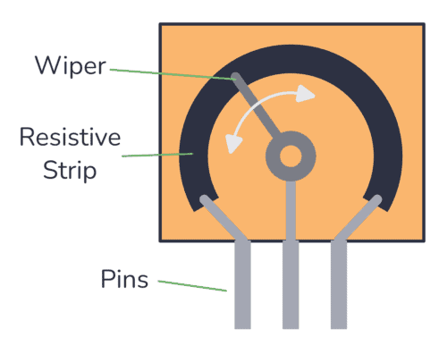
The Useless Halloween Machine

This year’s Halloween project is a useless machine built with 555 timers. It’s a coffin with a switch. When you flip it off, a dark force rises from the coffin and flips it back on.

Controlling a Servo with 555 Timers

The idea for this project came after we published the simple 555 PWM circuit that controls a DC motor using a PWM signal created by a 555 Timer. I started thinking about the idea of controlling a servo instead.

After some experimentation, I realized that the frequency changed too much when I changed the duty cycle. So my servo would only move at random times.

How to adjust the brightness of an LED

Do you want to adjust the brightness of your Light-Emitting Diode (LED)? If we break it down to the most basic, there are two ways to change the brightness of an LED:

  • Changing the resistance value.
  • Turning it on and off fast (Using PWM).

Below I’ll explain the two options and show you circuits you can build.

Arduino Shield Project LED matrix

How to Build a Touch Sensor Circuit

In this project, you will build a touch sensor circuit. It’s a cool and simple circuit that allows you to control an LED with the touch of a finger. And you only need three components, how cool right? You can build this circuit if you’re a total beginner. The Touch Sensor Circuit Diagram You only

Voltage Divider Tutorial For Beginners

A voltage divider is a circuit that creates a smaller voltage from an input voltage by using two resistors. You’ll see it in both simple and advanced circuits all the time. Here’s the basic setup:

The basic voltage divider circuit

It is useful for example for reading sensors like thermistors and photoresistors since it converts an unknown resistance into a voltage. Or to reduce the volume of an audio signal via a potentiometer.

You can find the output voltage by inserting the resistor values and the input voltage into the following formula:

V_{OUT} = \frac{R2}{R1+R2} \cdot V_{IN}

Or you can use the calculator a little bit further down on this page.

Once you know how it works, it’s much easier to see how circuits work. And it will let you calculate voltages at many different points in a circuit – which is often needed to understand it.

NOT Gate (Inverter) – Logic Gates Tutorial

A NOT gate (or inverter) is a logic gate where the output is the opposite of the input. So you can say that the output is NOT the same as the input. It’s often called an inverter since it inverts the input. The schematic symbol for an inverter is like a buffer, just with a

NOR Gate – Logic Gates Tutorial

A NOR gate is a logic gate where the output goes HIGH (or “1”) only if all its inputs are LOW (or “0”). The schematic symbol for a NOR gate is like the OR gate, just with a circle at the output to indicate that it’s an inverted version of OR. “NOR” stands for NOT-OR

OR Gate – Logic Gates Tutorial

An OR gate is a logic gate where the output goes HIGH (or “1”) if any of its inputs are HIGH. So if A OR B is HIGH, the output Q also becomes HIGH. If A or B is true, then Q is true Truth Table OR gates can have more than two inputs. But

NAND Gate – Logic Gates Tutorial

A NAND gate is a logic gate where the output goes LOW (or “0”) only if all its inputs are HIGH (or “1”). The schematic symbol for a NAND gate is like the AND gate, just with a circle at the output to indicate that it’s an inverted version of AND. “NAND” stands for NOT-AND

AND Gate – Logic Gates Tutorial

An AND gate is a logic gate where the output goes HIGH (or “1”) only if all its inputs are HIGH. So if the inputs A AND B are HIGH, the output Q will also be HIGH. If A and B are true, then Q is true Truth Table AND gates can have more than

XOR Gate – Logic Gates Tutorial

The XOR gate is a logic gate where the output goes HIGH (or “1”) if one – and only one – of its inputs are HIGH. XOR stands for Exclusive-OR. Check out its symbol and truth table below. If A and B are different from each other, then Q is true Truth Table XOR gates

XNOR Gate – Logic Gates Tutorial

An XNOR gate is a logic gate where the output goes HIGH (or “1”) only if both its inputs are equal. So if the inputs A and B are both HIGH or both LOW, the output Q will be HIGH. If A and B are the same, then Q is true Truth Table XNOR gates

Logic Gates: Understand The Basics of Digital Electronics

Logic gates are the basic building blocks of digital electronics. These are the components that we use for “doing stuff” with the 1s and 0s. You can combine them to create other building blocks like latches, flip-flops, adders, shift registers, and more. The basic logic gates are AND, NAND, OR, NOR, XOR, XNOR, and NOT.

Ohms Law – The Complete Beginner’s Guide

Ohms law is a simple formula that makes it easy to calculate voltage, current, and resistance. You can use it to find what resistor value you need for an LED, how much power your circuit uses, and much more. It’s one of the few formulas in electronics that you’ll use on a regular basis.

Cap Half Full #7 – Opamp basics and the 4000 series IC

In this episode, we talk about operational amplifiers (opamps) and the 4000 series IC that Øyvind has been writing a series of posts on. We also accidentally came across a funny error on Arrow’s website 😅.

Repairing Electronics: Electronic Candle

When visiting my parents for Christmas, my dad showed me three electronic candles that did not work anymore. He told me he had changed batteries and showed me that they did not show any signs of life.

I tried to get them to work as well, but no luck.

It sounded like a really fun device to repair, so I took them back to my lab in Oslo to try to see if I could figure out what the problem was.

When repairing electronics, you always have to start with what the problem is. Here, the problem was that nothing happened when connecting the batteries and pressing the ON switch.

When thinking about this problem I came up with two theories:

  • A dead LED inside the candle
  • Bad connections between batteries and the candle circuit