The Arduino blink LED circuit is a simple circuit that works great for starting to learn Arduino. Both the code and the connections are straightforward so that you can understand it with little to no background.
In this quickstart guide, you’ll learn how to connect an LED to an Arduino board and make it blink.
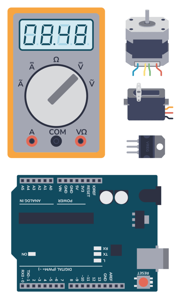
Parts Needed
- Arduino Uno
- Breadboard (and some breadboard wires)
- Light-Emitting Diode (LED) (Most LEDs will work)
- Resistor (220 Ω)
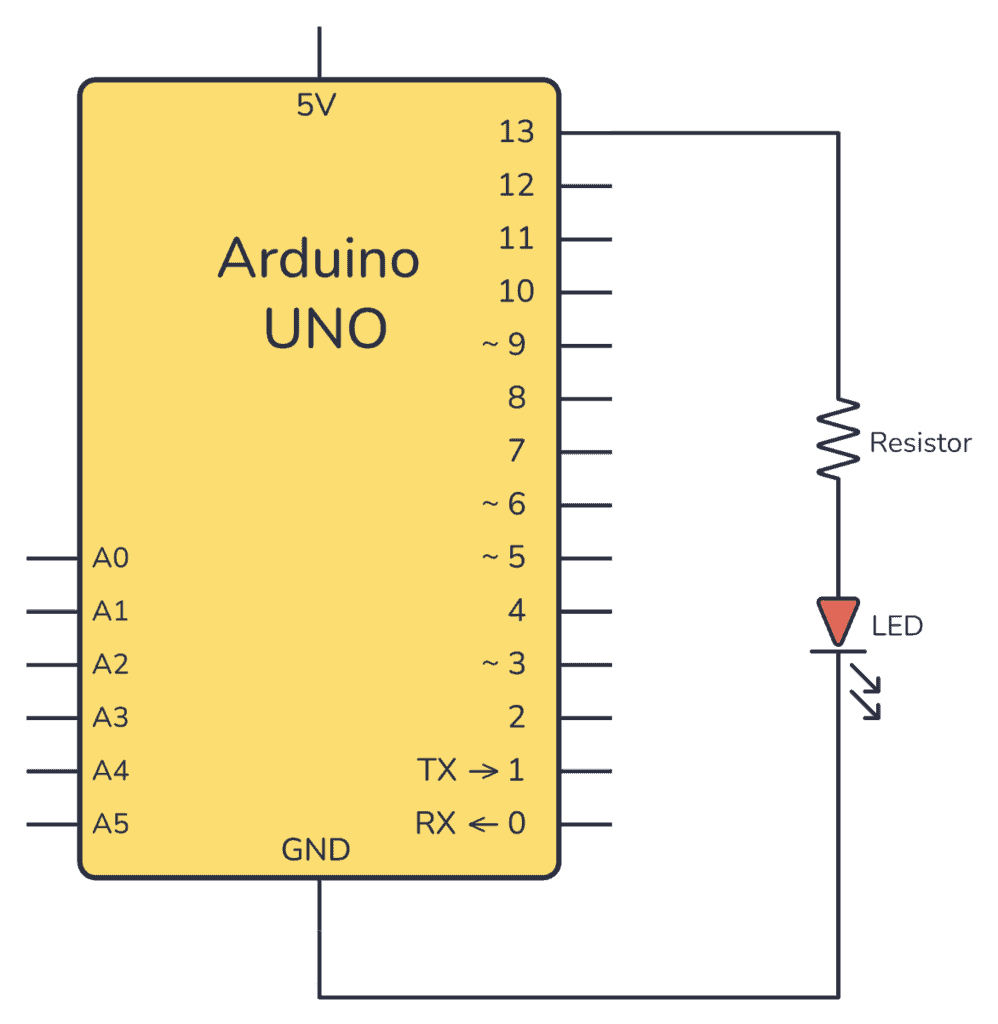
Arduino Blink LED Circuit
To connect an LED to an Arduino, you need a resistor in series with the LED. This is to limit how much current the LED pulls out of the Arduino pin. The value isn’t crucial but should be between 220 Ω and 1000 Ω.
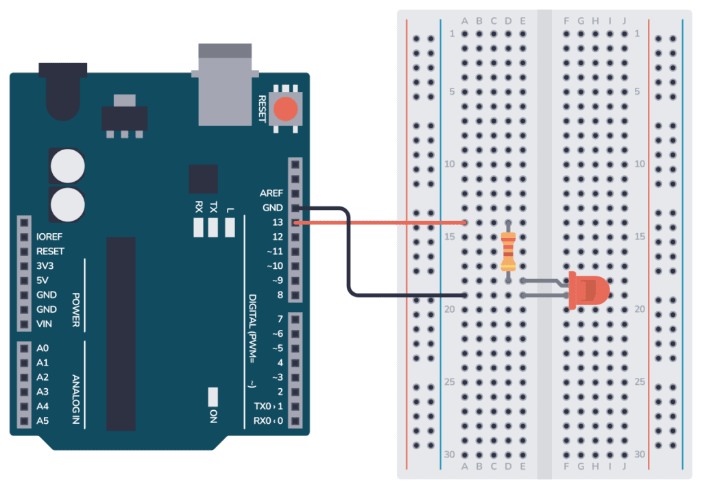
Connecting On a Breadboard
Here’s how you can connect the LED and the resistor to the Arduino by using a breadboard and a couple of cables:
Arduino Blink LED Code
All Arduino code is structured around the two main functions setup() and loop().
The setup() function runs only once when the Arduino board starts up. It is used for initializing variables, pins, and other settings.
The loop() function runs repeatedly after the setup() function has been executed. Whatever code is inside this function will be executed over and over again in an endless loop until the Arduino is powered off or reset.
Inside setup(), you need to configure pin 13 as an output.
Basic Electronics for Arduino Makers
Learn the basics that every Arduino maker should know, and it'll open you up to a world of possibilities! Sign up for my circuit tips by email and I'll send you the eBook:
Inside loop(), you need to set pin 13 HIGH, wait for a second, turn it low, then wait for another second.
Check out the complete code:
// The setup function that runs one time at startup
void setup() {
  pinMode(13, OUTPUT);     // Initialize digital pin 13 as an output.
}

// The main loop that continues forever
void loop() {
  digitalWrite(13, HIGH);  // turn the LED on (HIGH is the voltage level)
  delay(1000);             // wait for a second
  digitalWrite(13, LOW);   // turn the LED off by making the voltage LOW
  delay(1000);             // wait for a second
}
How the Code Works
Inside the setup() function there is only one line: pinMode(13, OUTPUT); This line sets pin 13 as an output so that we can use it to turn the LED on or off.
Inside the loop() function there are four lines:
digitalWrite(13, HIGH);This line turns on the LED connected to pin 13.HIGHsets the voltage of the pin to the logic HIGH level (usually 5V on most Arduino boards), which turns on the LED.delay(1000);This line adds a delay of 1000 milliseconds (1 second). It means the LED will remain on for one second before moving on to the next line of code.digitalWrite(13, LOW);This line turns off the LED by setting the voltage level of pin 13 to LOW (0V).delay(1000);This line adds another 1-second delay. So after the LED is turned off, the program waits for one second.
After this, the program goes back to the beginning of the loop() function where it turns the LED on again, and the process repeats.
This code results in a LED (connected to pin 13) blinking on and off repeatedly, with each state (on and off) lasting for one second.
More Arduino Tutorials
Basic Electronics for Arduino Makers
Learn the basics that every Arduino maker should know, and it'll open you up to a world of possibilities! Sign up for my circuit tips by email and I'll send you the eBook: