fbpx

Capacitors in Parallel

How to connect capacitors in parallel

When you connect capacitors in parallel, you connect them alongside each other. And the result becomes a capacitance with a higher value. In this guide, you’ll learn why it works like that, how to calculate the resulting capacitance, and some examples of this in practice. As you’ll soon see, this is actually very simple. How

The Useless Halloween Machine

Drawing of useless machine circuit soldered

This year’s Halloween project is a useless machine built with 555 timers. It’s a coffin with a switch. When you flip it off, a dark force rises from the coffin and flips it back on. This project uses two 555 timers to control the position of a servo motor, which was a fun challenge in itself.

Check out the video below to see the result:

How to adjust the brightness of an LED

Do you want to adjust the brightness of your Light-Emitting Diode (LED)? If we break it down to the most basic, there are two ways to change the brightness of an LED:

  • Changing the resistance value.
  • Turning it on and off fast (Using PWM).

Below I’ll explain the two options and show you circuits you can build.

Arduino Shield Project LED matrix

How to Build a Touch Sensor Circuit

Touch LED Circuit protoboard

In this project, you will build a touch sensor circuit. It’s a cool and simple circuit that allows you to control an LED with the touch of a finger. And you only need three components, how cool right? You can build this circuit if you’re a total beginner. The Touch Sensor Circuit Diagram You only

Voltage Divider Tutorial For Beginners

The basic voltage divider circuit

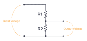
A voltage divider is a circuit that creates a smaller voltage from an input voltage by using two resistors. You’ll see it in both simple and advanced circuits all the time. Here’s the basic setup:

The basic voltage divider circuit

It is useful for example for reading sensors like thermistors and photoresistors since it converts an unknown resistance into a voltage. Or to reduce the volume of an audio signal via a potentiometer.

You can find the output voltage by inserting the resistor values and the input voltage into the following formula:

V_{OUT} = \frac{R2}{R1+R2} \cdot V_{IN}

Or you can use the calculator a little bit further down on this page.

Once you know how it works, it’s much easier to see how circuits work. And it will let you calculate voltages at many different points in a circuit – which is often needed to understand it.

NOT Gate (Inverter) – Logic Gates Tutorial

NOT gate truth table and symbol

A NOT gate (or inverter) is a logic gate where the output is the opposite of the input. So you can say that the output is NOT the same as the input. It’s often called an inverter since it inverts the input. The schematic symbol for an inverter is like a buffer, just with a

NOR Gate – Logic Gates Tutorial

NOR gate symbol and truth table

A NOR gate is a logic gate where the output goes HIGH (or “1”) only if all its inputs are LOW (or “0”). The schematic symbol for a NOR gate is like the OR gate, just with a circle at the output to indicate that it’s an inverted version of OR. “NOR” stands for NOT-OR

OR Gate – Logic Gates Tutorial

OR gate truth table and symbol

An OR gate is a logic gate where the output goes HIGH (or “1”) if any of its inputs are HIGH. So if A OR B is HIGH, the output Q also becomes HIGH. If A or B is true, then Q is true Truth Table OR gates can have more than two inputs. But

NAND Gate – Logic Gates Tutorial

NAND truth table and symbol

A NAND gate is a logic gate where the output goes LOW (or “0”) only if all its inputs are HIGH (or “1”). The schematic symbol for a NAND gate is like the AND gate, just with a circle at the output to indicate that it’s an inverted version of AND. “NAND” stands for NOT-AND

AND Gate – Logic Gates Tutorial

AND gate truth table and symbol

An AND gate is a logic gate where the output goes HIGH (or “1”) only if all its inputs are HIGH. So if the inputs A AND B are HIGH, the output Q will also be HIGH. If A and B are true, then Q is true Truth Table AND gates can have more than

XOR Gate – Logic Gates Tutorial

XOR gate truth table and symbol

The XOR gate is a logic gate where the output goes HIGH (or “1”) if one – and only one – of its inputs are HIGH. XOR stands for Exclusive-OR. Check out its symbol and truth table below. If A and B are different from each other, then Q is true Truth Table XOR gates

XNOR Gate – Logic Gates Tutorial

XNOR gate truth table and symbol

An XNOR gate is a logic gate where the output goes HIGH (or “1”) only if both its inputs are equal. So if the inputs A and B are both HIGH or both LOW, the output Q will be HIGH. If A and B are the same, then Q is true Truth Table XNOR gates

Logic Gates: Understand The Basics of Digital Electronics

Collection of all the logic gate symbols

Logic gates are the basic building blocks of digital electronics. These are the components that we use for “doing stuff” with the 1s and 0s. You can combine them to create other building blocks like latches, flip-flops, adders, shift registers, and more. The basic logic gates are AND, NAND, OR, NOR, XOR, XNOR, and NOT.

Ohms Law – The Complete Beginner’s Guide

Ohms law cartoon

Ohms law is a simple formula that makes it easy to calculate voltage, current, and resistance. You can use it to find what resistor value you need for an LED, how much power your circuit uses, and much more. It’s one of the few formulas in electronics that you’ll use on a regular basis.

Cap Half Full #7 – Opamp basics and the 4000 series IC

Pinout for the 4016 IC

In this episode, we talk about operational amplifiers (opamps) and the 4000 series IC that Øyvind has been writing a series of posts on. We also accidentally came across a funny error on Arrow’s website 😅.