To be able to read schematics you must know the basic schematic symbols used in electronics. But you don’t need to memorize them all. To start with, it’s usually enough to know the battery, resistor, capacitor, transistor, diode, LED, and switch.
Later when you come across symbols you don’t know, you can come back here to identify what it is.
Below is an overview of the most used symbols in circuit diagrams.
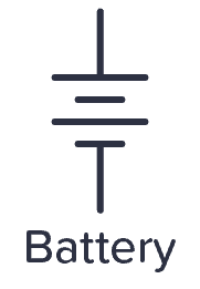
Battery
The symbol for a battery is shown below.
A large and a small line is suppose to represent one battery cell so that the image below would suggest a two-cell battery of 3 V. But usually people just draw the battery symbol with one or two cells no matter what voltage it is.
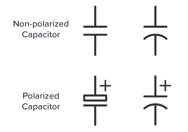
Capacitor
Capacitors are either polarized or not. The symbols that are commonly used for the two are shown below.
A polarized capacitor is marked with a “+” sign. It is important to distinguish between these two because the polarized capacitor needs to be placed correctly according to the “+” sign.
Resistor
The schematic symbol of the resistor are drawn in two different ways. The american style resistor is drawn as a zigzag resistor while the european style resistor is drawn as a rectangular resistor.

Get Our Basic Electronic Components Guide
Learn how the basic electronic components work so that circuit diagrams will start making sense to you.
Even though I’m from Europe, I like to draw the zigzag version. I think it is easier to draw and looks better.


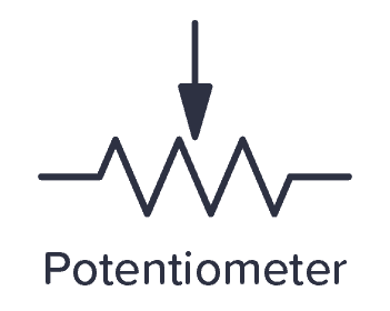
Potentiometer
The potentiometer is drawn in several different ways. The symbol is usually drawn as a resistor with an arrow across it or pointing down on it as the one below.
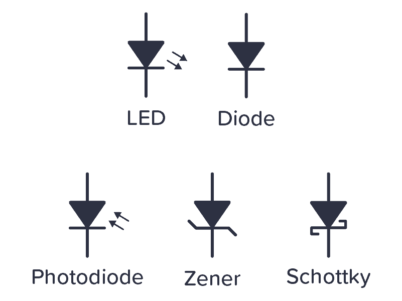
Diode
The diode family has several different symbols because there are several different types of diodes. Below is a standard diode, a Zener diode, a Schottky diode, and a Light-Emitting Diode (LED).
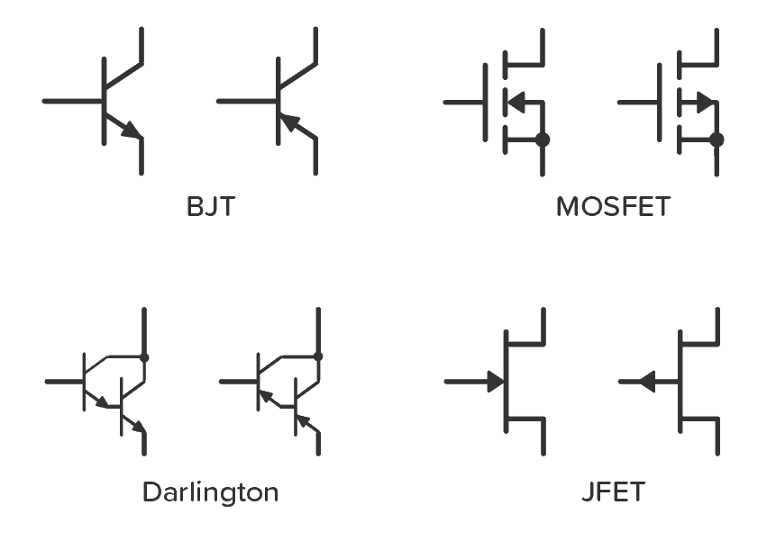
Schematic Symbols of a Transistor
The most common transistor types are the Bipolar Junction Transistor (BJT), Darlington Transistor, and Field-Effect Transistor (FET). The schematic symbols for these types are shown below:
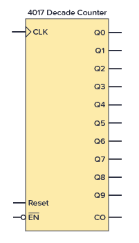
Schematic Symbol for an Integrated Circuit
An Integrated Circuit (IC) is usually shown as a rectangular box with pins. Below, an example of the CMOS IC 4017 is shown.
Logic Gates
Here are the schematic symbols for the logic gates:

Inductor
The inductor symbol looks like a coiled wire as this is what an inductor essentially is.

Transformer
The symbol of the transformer looks like two inductors with something in between them. That’s because that’s basically what a transformer is.

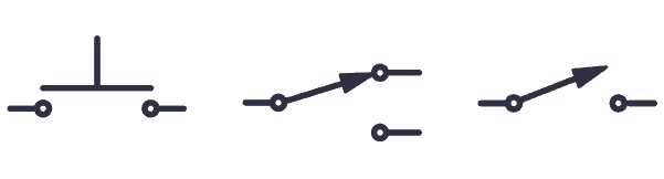
Switch
A switch can be represented in numerous ways in a circuit diagram. Below is a few examples:
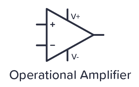
Operational Amplifier
The operational amplifier or “opamp” is represented as a triangle with two inputs and one output. In some cases, the power supply pins are removed, but you still need to connect them for it to work.
Power symbols
In larger circuit diagrams, you usually have a lot of connections to the power supply. To simplify, it’s common to use power symbols for ground and VDD (or VCC) as shown below.

In circuits where you have a dual supply, that is positive, neutral, and negative – you usually have a third power symbol that looks like the VDD symbol, just upside down.
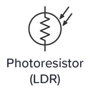
Photoresistor
The symbol for a photoresistor – or Light-Dependent Resistor (LDR) – looks like a resistor in a circle with arrows pointing inwards.
Crystal
The crystal is a component used to create a stable clock frequency, often for microcontrollers. In circuit diagrams it looks like this:

Fuse
Fuses are often used in higher-voltage circuits. The fuse symbol looks like this:

More Schematic Diagram Tutorials
Get Our Basic Electronic Components Guide
Learn how the basic electronic components work so that circuit diagrams will start making sense to you.

