In this tutorial, you’ll learn how to build a 555 PWM Circuit. The 555 timer is one of the most popular integrated circuits for hobbyists. And one of the cool features is its ability to produce a PWM signal.
The circuit is fairly easy to make, and it can control a great variety of things, including motor speed and LED brightness.
555 PWM Circuit Diagram

Note: For VCC, you can use anything from 5V to around 15V. What to choose will depend mostly on the size of the motor you are using. If it is small, you can control everything with 5V.
Components Needed
- A DC motor
- 555 Timer IC
- Q1: IRLIZ44N MOSFET (or any other n-type MOSFET with a suitable gate threshold)
- RV1: 10 kΩ Potentiometer
- R1: 1 kΩ Resistor
- R2: 5 kΩ Resistor
- C1: 100 nF Ceramic Capacitor
- C2: 1 nF Ceramic Capacitor
- D1-D2: 1N4001 Diode
How the PWM 555 Circuit Works
The PWM 555 Circuit is known as an improved 555 oscillator. This is because it makes use of a couple of extra components to improve the output signal that the most common astable multivibrator circuit would give. It uses R1 and C1 to control the frequency of the signal. And you can modify the duty cycle with RV1.
With the duty cycle, you can control the average voltage in the output of the 555, which makes it a very functional analog controller for your projects. For example to control the speed of a motor or dim an LED.
In the example below, we’ll connect a motor.
How to Build the PWM 555 Circuit
Here you can see the circuit already built:
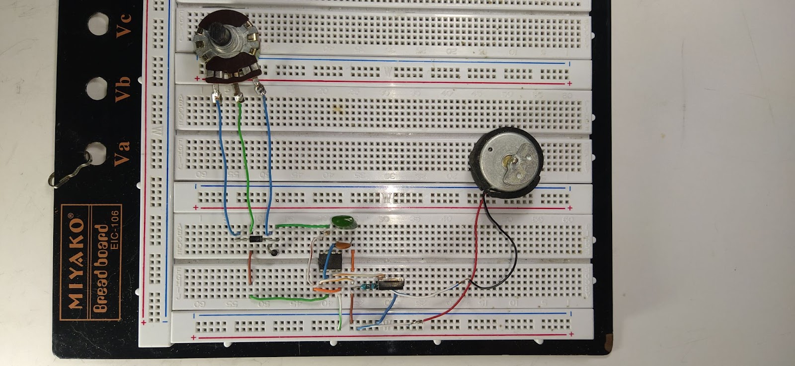
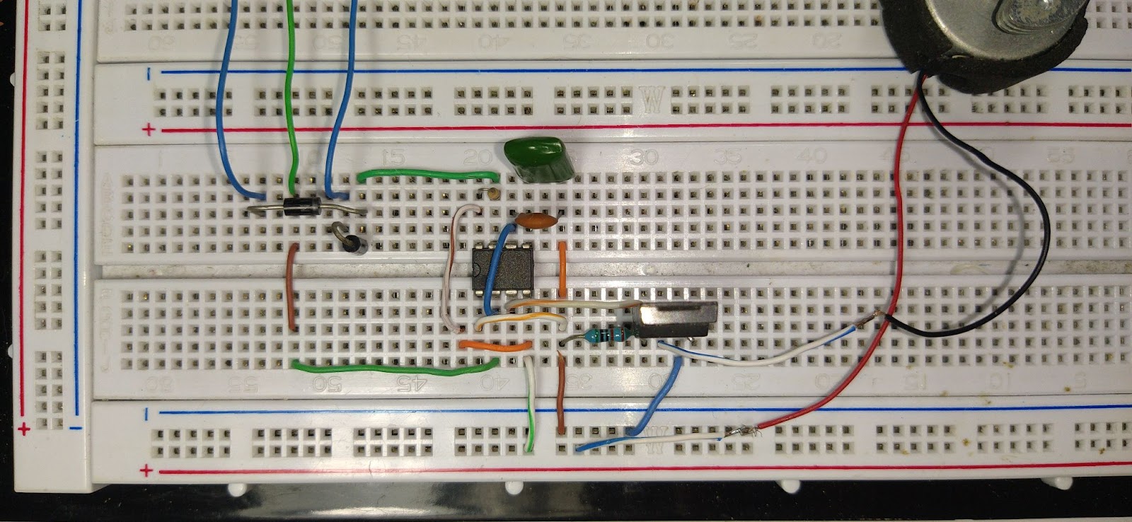
Here is a closer look, be aware of the placement of R1 and one of the diodes, which are placed in a way to not take too much space:

Get the 555 Timer Cheatsheet
A super helpful reference that makes it easy to design circuits, so that you can build oscillators, timer circuits, and more in no time.
The Result
In this video, you will be able to see the output of the 555 PWM Circuit, and how the duty cycle changes while changing the value of the potentiometer. It is also visible that the change in speed of the motor depends on the duty cycle.
The downside with this circuit is that the frequency of the output also varies quite a bit, which means it does not work well with servo motors that require a specific frequency. If you need a specific and stable frequency, check out this project on controlling a servo motor with the 555 Timer.
More 555 Timer Tutorials
Get the 555 Timer Cheatsheet
A super helpful reference that makes it easy to design circuits, so that you can build oscillators, timer circuits, and more in no time.