• Skip to primary navigation
  • Skip to main content
  • Skip to primary sidebar
  • Skip to footer
Build Electronic Circuits

Build Electronic Circuits

Electronics explained in a simple way

  • Start Learning
    • Basic Electronics
    • Digital Electronics
    • Circuits
    • Practical Skills
      • Printed Circuit Boards
    • Microcontrollers
      • Arduino
    • Maker Lifestyle
      • Podcast
    • Academy
  • About Me
  • Blog
  • Academy
  • Contact
You are here: Home / Circuits / Build an Atari Punk Console this evening

Build an Atari Punk Console this evening

August 15, 2018 By Øyvind Nydal Dahl 11 Comments

Do you want a fun and easy-to-build circuit? Here’s the simple, but fun Atari Punk Console – with schematics and parts list. It’s a quick build, so you can easily build it during an evening.

It takes its name from the old Atari computers of the 80s because it makes similar sounds.

And after my (not-so-intense) research (I basically just read about it on Wikipedia), I’ve come to learn that the circuit was first published in a Radioshack magazine in 1980.

Here’s a short clip of me playing with the circuit I built:

This was the first really cool sound-creating circuit I ever built.

Before building this I had only built simple tone-generators. So the first time I hooked this baby up, I was playing with it for an hour – making everyone else in the makerspace crazy.

This circuit is perfect if you have built a couple of simple circuits before and want more interesting stuff.

Or if you’re just looking for something really cool to build.

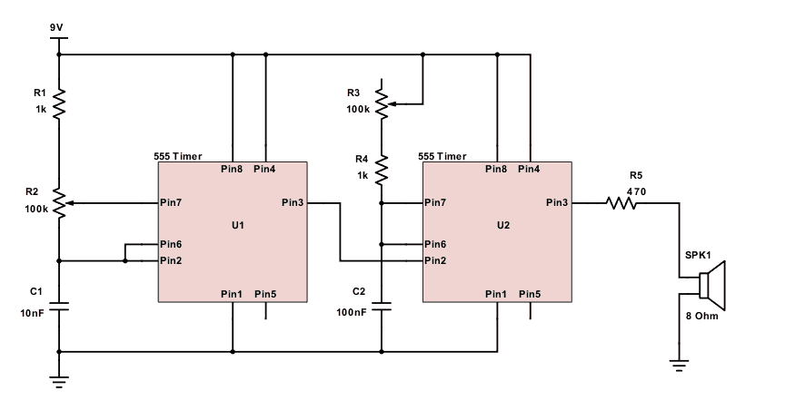
Atari Punk Console Circuit Diagram

Atari punk console circuit diagram

Parts List

To build the Atari Punk Console, you need:

Atari punk console on breadboard

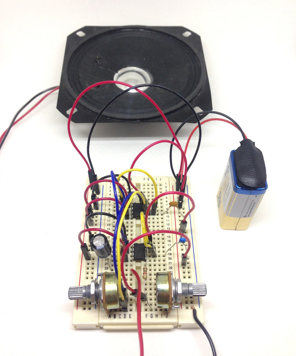
  • A breadboard board to build it on
  • Jumper wires
  • Speaker (minimum 0.3W)
  • Two 555 timer chips
  • C1: 10 nF capacitor
  • C2: 100 nF capacitor
  • R1, R4: 1 kΩ resistors
  • R2, R3: 100k potentiometers
  • R5: Resistor, 470 Ω

These are all standard components and pretty easy to get your hands on. Not sure where to get components? Check out my list of where to buy components and tools.

Description

This is a refreshing alternative to the theoretical circuits you see in many books.

The circuit uses two 555-timers.

The 555 Timer needs a few capacitors and resistors to set the tone or the pulse length.

By combining one that sets the frequency and one that sets the pulse length, you can create some crazy sounds.

Atari Punk Console Kit

You can easily find all the components yourself and build it on a breadboard like described above. But if you prefer an even more convenient way – you could get yourself an Atari Punk Console kit.

The advantage of the kit is that you get everything you need in one go. And it also has a nice casing to fit the circuit into.

Have you tried building this circuit? How did it go?

Let me know in the comments below!

Filed Under: Circuits

Reader Interactions

Comments


  1. Clayton Benignus says

    August 16, 2018

    Can we have a followup explanation of how that circuit works? Also, how would you boos the sound with an OpAmp?

    Reply

    • admin says

      August 18, 2018

      Good suggestions. I can’t promise anything, but I’ll keep those in mind.

      Reply

  2. willis says

    August 16, 2018

    wonderful!thank you for your Explanation and patience,i have learned a lot

    Reply

  3. Gbenga Odukale says

    August 16, 2018

    Many thanks for sharing.

    Reply

  4. Ronald Boucher says

    August 16, 2018

    I noticed that the 100 ohm gets really hot, as there’s too much DC current is being pulled through. Only AC should go to the speaker.

    I’ll send you the email of the image to be modified, as I can’t upload the image.

    Reply

    • Ronald Boucher says

      August 16, 2018

      What I mean is that the speaker needs to have AC coupling output from 2nd 555 timer pin 3 to speaker, not DC coupling.

      Reply

    • admin says

      August 17, 2018

      Hey Ron,

      Thanks! I appreciate your feedback. The output from the circuit should always be alternating, that’s why I skipped the coupling capacitor. And I like to keep these circuits as simple as possible so that beginners think “I could build that too!” – so no filtering either.

      The idea of the 100-ohm resistor was to make it possible to use really low-watt speakers without destroying them. But I totally forgot to take into account the power dissipation of the resistor! So thanks a lot for pointing that out.

      Those using speakers that can handle 1.25W or more can skip the resistor and connect the speaker directly for a simpler circuit. Or use Ron’s version which is the more “proper” way of doing it with coupling capacitor and filter.

      Best,
      Oyvind

      Reply

      • Zefyr says

        September 18, 2019

        How do you get the value of 1.25W?

        Reply

        • admin says

          September 20, 2019

          I think I made a mistake on the 1.25W. Not sure how I reached that.

          There are three things to keep in mind:
          -The maximum wattage of the speaker
          -The maximum current from the 555 Timer
          -The watt rating of the resistor R5

          To be sure you don’t pull more than the maximum 200 mA, the total resistance of the speaker + the resistor R5 must be 45 Ohm. (9V / 45 Ohm = 0.2A)

          If you have an 8-ohm speaker with 0.2A flowing, that becomes 0.32W (P = I*I*R). So with a speaker rated for around 0.3W or more, you’re good to go.

          But standard resistors are usually rated at 0.25W. If the resistor is for example 40 Ohms, we get 0.2A * 0.2A * 40 Ohm = 1.6W power dissipation in the resistor. Way too much for a 0.25W resistor.

          That’s why the resistor (if using 0.25W resistor) should be at least 324 ohm. P = V*V/R = 9*9/324 = 0.25W.

          So I chose 470 Ohm to be well within that limit.

          Reply

          • Zefyr says

            September 21, 2019

            Super clear, thank you! If leaving out R5 entirely though, then it seems like aside from the wattage the speaker would need to be at least 45 Ohm on its own, right?


          • admin says

            September 21, 2019

            Yes, that’s correct.

Leave a Reply Cancel reply

Your email address will not be published. Required fields are marked *

Primary Sidebar

Search:

Footer

Topics

  • Basic Electronics
  • Digital Electronics
  • Circuits
  • Practical Skills
  • Microcontrollers
  • Maker Lifestyle
  • Newsletter Archive

Social:

  • Facebook
  • Twitter
  • YouTube

Products

  • Electronics Course
  • Other Products

Copyright © 2022 · Ohmify AS · Terms and Conditions · Privacy Policy