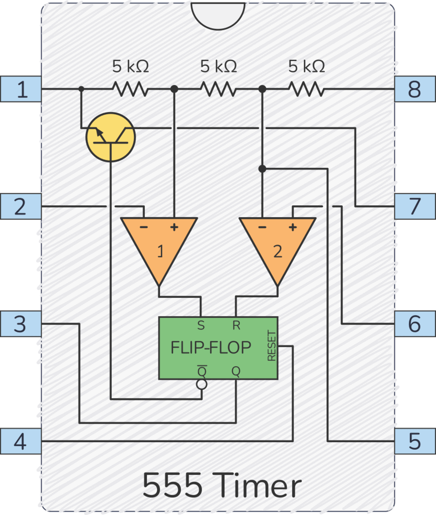
The 555 timer works by using three 5 kΩ resistors to divide the supply voltage in three. Two comparators compare these voltages to the input voltage, then sets or resets a flip-flop accordingly.
Below is a diagram showing what the 555 timer looks like on the inside:

How the 555 Timer Works
At the top of the diagram above, you have three 5 kΩ transistors between VCC and GND.
These resistors divide the VCC voltage in three.
Many think that these resistors are the reason for the name “555.” But according to an interview with the inventor, it was actually chosen at random.
Below the resistors, there are two triangles. These are comparators. If the comparator input marked with + has a higher voltage than the one marked with −, the output is high; otherwise, the output is low.

The 5k resistors set fixed voltages for each of the comparators: one-third of the VCC voltage goes to the positive (+) input of comparator 1, and two-thirds of the VCC voltage goes to the negative (–) input of comparator 2.
The green box is an SR Latch. It is a simple memory device with two states: output high and output low.

Get the 555 Timer Cheatsheet
A super helpful reference that makes it easy to design circuits, so that you can build oscillators, timer circuits, and more in no time.

It has two inputs, set (S) and reset (R). S sets the output (Q) to high and R resets it to low.
Q is always the opposite of Q.
Comparator 1 checks if the voltage on the Trigger pin is below 1/3 of VCC. If it is, it sets the flip-flop so that the Output pin becomes high.
Comparator 2 checks if the voltage on the Threshold pin is above 2/3 of VCC. If it is, it resets the flip-flop so that the Output pin becomes low.
The flip-flop also controls a transistor that connects the Discharge pin to ground when the output is low.

Summary
The pins responsible for making the Output (pin 3) go high or low are the Trigger (pin 2) and the Threshold (pin 6).
The Trigger pin is responsible for setting the output high. When the voltage on the trigger pin goes lower than one-third of VCC, comparator 1 outputs high and sets the flip-flop high, which in turn sets the Output pin high.
Pin 6 is labeled Threshold; when its voltage exceeds two-thirds of the VCC, it is responsible for resetting the Output back to low.
Want to learn how to use it? Check out the 555 timer tutorial.
More 555 Timer Tutorials

Get the 555 Timer Cheatsheet
A super helpful reference that makes it easy to design circuits, so that you can build oscillators, timer circuits, and more in no time.
