The RC delay element is a way to create a time delay in your circuit by connecting a resistor and a capacitor. It’s super simple. And very useful.
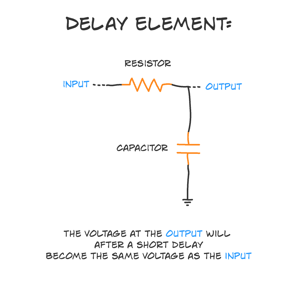
The ‘R’ is a resistor, and the ‘C’ is a capacitor. That’s where the ‘RC’ comes from. And here’s how you connect the two:
How does it work?
A capacitor is kinda like a tiny little battery. You can charge it with a voltage. And you can use this voltage for a short time until the capacitor is discharged.
The time it takes for the voltage to rise across the capacitor becomes our time delay.
A capacitor with a higher Farad value can store more energy than one with a smaller value. Therefore it also takes more time to charge a high-value capacitor versus a small-value capacitor.
The “speed of the charging” is determined by how much current that flows through the capacitor.
The more current that flows, the faster it charges.
If we connect the capacitor directly to the battery, there is no restriction on the amount of current that flows through the capacitor (other than the batteries own maximum current capacity).

Get Our Basic Electronic Components Guide
Learn how the basic electronic components work so that circuit diagrams will start making sense to you.
So a lot of current flows, the capacitor charges really quick, and the delay becomes very small.
That’s where the resistor comes into play.
The task of the resistor is to reduce the flow of current to the capacitor to slow down the time it takes to charge it.
The RC Time Constant
You can calculate the delay time of your RC delay element with a simple formula:

That’s the RC time constant, also called tau, which is written like τ.
It gives you the time it takes for the voltage to rise from zero to approximately 63.2% of the voltage you apply.
If your RC delay element has a resistor of 10 kΩ and a capacitor of 100 µF, then your time delay becomes:

Put that into a calculator and you’ll get a time delay of 1 second.
More Basic Electronics Tutorials

10 Simple Steps to Learn Electronics
Electronics is easy when you know what to focus on and what to ignore. Learn what "the basics" really is and how to learn it fast.
Hello from arturo @ [email protected]
Just finished reading your whole program
Hey Arturo, I hope you enjoyed it!
Hey there,
I am a new reader and have spent substantial time with your blog during Easter. I have almost read all articles and love your style.
I have some quite basic questions towards this schematic. I thought, voltage splits up equally in a parallel circuit, so why does (2) not immediately have full voltage? I would understand if the current starts low and rises high.
A follow-up question that I would love to hear an answer to is: How can I calculate current/voltage development over time for both capacitor and (2) during the charging process?
I hope, you will publish many more articles, I really enjoy reading them!
Hi Michael,
Glad you enjoy my articles!
“I thought, voltage splits up equally in a parallel circuit, so why does (2) not immediately have full voltage?”
The resistor and capacitor are not connected in parallel. To be connected in parallel, both side of both components must be connected. Also, I’m not sure what you mean by “voltage splits up equally in a parallel circuit”….
But maybe this will become clearer when you look at the calculation of voltage over time. Learn about that here:
https://www.electronics-tutorials.ws/rc/rc_1.html
Oh sorry, I missed some crucial detail.
I mean, if I had some extension of the schema at (2), so that the current and voltage that arrive there actually arrive somewhere. I mean, the current/voltage that arrives at (2) should have some purpose. I could, for example, put another resistance there like in this schematic: https://www.google.com/url?sa=i&rct=j&q=&esrc=s&source=images&cd=&cad=rja&uact=8&ved=2ahUKEwi1rZKBq-bhAhXRIVAKHaXvBcsQjRx6BAgBEAU&url=https%3A%2F%2Fwww.youtube.com%2Fwatch%3Fv%3D4I5hswA45CM&psig=AOvVaw3HDX8ZMLzu2xpvE8riLY2N&ust=1556112999420315
Now, the new resistor R2 and the capacitor are, per my understanding, connected in parallel, so that the capacitor and LED should have the same voltage. I mean that in the same sense as, e.g., wikipedia states it: https://en.wikipedia.org/wiki/Series_and_parallel_circuits#Voltage_2
The circuit in your link has a resistor and capacitor wired in series, this is not the case that I mean here.
Does my question get clearer? I only find material for RC circuits with AC instead of DC, or articles that do not explicitly describe how current/voltages behave during the charging process but only when the capacitor is fully charged.
sorry, this is the link with the image: https://i.ytimg.com/vi/4I5hswA45CM/maxresdefault.jpg
Ok, I think I know what you’re asking. You’re saying that if we ignore C in the circuit you linked to (https://i.ytimg.com/vi/4I5hswA45CM/maxresdefault.jpg), then the voltage would split up equally, right? So why doesn’t it happen right away when the C is there?
First. the voltage doesn’t split equally, but it splits based on the voltage divider formula:
Vout = Vin * R2/(R1 + R2)
Only when the two resistors have the same value, the voltage is split equally.
Vout would be the same point as (2) in my circuit.
In the case where we also have the capacitor, R2 in the formula above would be replaced by the total resistance of R2 and C in parallel.
A capacitor also has a resistance. But it’s resistance varies depending on how “charged” it is.
When it’s completely discharged, its resistance is close to zero. When it is completely charged, its resistance is theoretically infinitely high.
So, when the capacitor is completely discharged:
R2 is in parallel with 0 Ohms. Which gives a total resistance of 0 Ohms. Which gives a voltage of 0 V for Vout – or (2).
When the capacitor is completely charged:
R2 is in parallel with a resistor of infinitely high resistance.. Which gives a total resistance equal to the value of R2. Which gives a voltage out that basically ignores that the capacitor is there.
Hi, I’m trying to use this circuit to create a 500ms delay on the output of an IC going to a clock for a flip flop, which is not working. My best guess is that because low for the IC is <1.2V not 0 the calculation above no longer applies? Wondering if you have any suggestions on how to create such a time delay?
The easiest would be to just increase the resistor and/or capacitor values. If you want to calculate exactly 500 ms, you can find more info on how the voltage across the capacitor increases with time:
https://www.electronics-tutorials.ws/rc/rc_1.html
If you hooked the RC circuit up to an LED and then switched on the power, it would take however long the delay is for the LED to turn on, right?
Also, what are some higher-level applications of this circuit? It seems like resistors and capacitors are used a lot to configure the settings of ICs, but I’m not totally sure how that works. Could you explain that to me, or point me to some good learning material?
Thanks!
Yes, if you hook up an LED to this you’ll get a delay. But note that the delay is for the voltage to reach about 63% of the input voltage. Your LED might turn on already at for example 40%, depending on the input voltage and your LED.
This is for example used in audio filters. Or it is used to create oscillators. A simple example is to blink a light: https://www.build-electronic-circuits.com/blinking-led-circuit/
If a capacitor and resistor is used to configure an IC, it’s most likely to set the frequency of an oscillator in the IC.
Hello. I just read your article and I love it. I’m trying to custom build my own trigger for a Qualcomm QC battery bank to output 12v to the (dumb) device it’s charging. I found a simple circuit that will create this “handshake”, but it requires that I manually press a NO switch after waiting at least 1.5 seconds.
I want to bypass the manual switch, so I started searching for a delay timer, which unfortunately I could not find anything small, or simple enough for my project. Then I searched the 555 timer and with another persons schematic and in-depth explanation of how to build the circuit, I learned that the capacitor is what causes the delay. So I searched for a simpler circuit and came across your article.
Anyway, the circuit seems perfect for what I need, but I have just one question – how will the capacitor discharge? Is it automatic? I’m a novice at circuit building so there’s a lot I haven’t learned yet. I definitely need the delay to happen each time I plug in the charger. Thanks for your help
Hi Vail,
The capacitor will discharge in the same way as a battery discharges – when you have something connected between the positive and the negative side of the capacitor that creates a path for the current to flow.
That said, capacitors aren’t perfect and won’t keep their charge forever.
I find the caption confusing.
I imagine connecting a battery to (1) and a volt meter to (2).
The voltage at (1) would immediately be V+, the battery voltage. The voltage at (2) would rise more slowly as the capacitor charges through the resistor. Eventually, the voltages at (1) and (2) become equal, but assuming the power is connected to (1) then (2) comes up to full voltage more slowly than (1).
Are (1) and (2) reversed in the caption, perhaps? Or are you assuming a different scenario, such as applying power to (2)?
Hey John! You’re right, that was an awkward sentence. I updated the caption to make it more clear. Thanks for pointing it out!
This is a bit old at this point, but I figured I’d ask anyway.
Is there any preferred ration in the resistor value to capacitor value? In other words, is a 30000uf cap and 100ohm resistor preferable to a 10000ohm resistor and a 300uf cap? Or does those values not have any impact in the end?
I built my daughter a tube amp with two switches wired in a way that she can turn either on and turn on the filaments and then after a delay, she can flip the other switch to apply B+. I wanted to give her an indicator that it’s ready for high voltage by building in some LED lighting that triggers after 20-30seconds. I’m going to wire up LEDs in series and use a constant current source to keep them all at 20ma. Can this RC circuit be used in front of the CCS in a circuit like this or will it impact the CCS performance in some way?
Capacitors have leakage current – a current that just goes through them without charging the capacitor. This current is larger the higher the capacitance value.
The resistor limits the current. The larger the resistor, the lower the current. So there will be a point where your resistor limits the current so much that the current just flows through the capacitor without charging it.
It didn’t understand what the CCS circuit was.
A late reply but maybe another coming will find it useful.
Particularly for capacitors, you will find that the larger the value the bigger the component, a 30000uf cap at 25V would be huge (28mm dia and 220mm long would be typical) and cost $15. A 300uf cap at 50V would be smaller (6mm dia and 13mm long would be typical) and cost $6. A 10uf cap would be smaller again (4mm dia and 6mm long typically) and cost less than a dollar.
Resistors do als vary in size depending on the amount of current to be drawn. The smaller the value the higher the current. A 300kOhm resistor would be 3mm dia and 12mm long (to match your now 10uF cap.
If your CCS is going to supply 20mA, then it would be overloaded by the big 30000uF cap.
You need to keep the caps small but not too small. A good rule of thumb is to keep your resistor values less than 330kOhms.
The type of component is also important. in this case any type resistor you buy would be ok. For the cap I recommend an electrolytic type as a tantalum can fail short circuit. Make sure to rate the voltage more than 3 times the voltage you are intending to use otherwise the capacitor will fail early
Hi there,
I’ve just found this article, I’m wanting to know if I could use this type of circuit to turn on a set of LEDs I.e. 24vdc marker lights on a Big rig, allowing the LEDs to turn on sequentially, then remain on
Any assistance appreciated
Thanks
Darren
I generally object to comparisons between a capacitor and a battery. It is somewhat true that a capacitor acts momentarily like a battery. But they are really different types of components for different purposes. A battery generates a voltage from chemical reactions. It’s a energy conversion process. A battery can remain “charged” (able to provide a current) typically for many months or years. And the voltage remains relatively constant for the life of the battery, independent of the amount of current that is being used (within limits of course). It’s sort of like a lake that is constantly filling with rain water, and can be drained indefinitely. Conversely, a capacitor is more like a small holding tank for charge. It does not convert energy – merely provides a short-term mechanism for this storage. As soon as current begins to trickle out, the voltage begins to drop. Practically speaking, capacitors can only hold charge for a brief period of time- in most circuits for very small fractions of a second, before needing to be recharged. (Don’t put this to a test on a large-value high-voltage power capacitor, however. These can still retain charge for seconds or minutes after the power has been removed. Still we are talking a very short period of time compared to the life of the batteries in the Eveready bunny.) Mathematically in circuit analysis, a battery is usually treated as a constant source. Capacitors, on the other hand, are treated as tank of fixed capacity, that is constantly being filled and drained as the circuit does its designed activity.
Hi, I am hoping to create a small time delay (a slug) on a 12v automotive circuit. The 12v flasher turn signal provides a pulsed input to my camera controller. The camera controller, when it receives a LHS flasher turn input, selects and displays the LHS camera. Same for the RHS. For some bizarre reason it works great on one side and great most of the time, but not always on the other. Almost as though the flasher pulse is slightly longer on one side than the other. I’ve checked the bulb wattages (as this dictates the rate of flash – oldie world bimetallic strip flasher) and they are the same and there is certainly no perceivable difference in flash frequency. A resistor / capacitor circuit, with the flasher turn signal on the Input side and the pulse to the camera controller on the output side, with a diode fitted on the input side to prevent back feed to the flasher turn signal circuit appears to be a cheap and easy fix. What resistor / capacitor values would I need to create a 1 second delay? Many thanks in advance. Les
I would like to use something like this to sense when power is applied to a 12 vdc circuit. It needs to sense then stop. Will this work the way I want if I invert the circuit and place the capacitor on top and the resistor below (on end at ground)? I want the output of this to feed one leg of a complex OR gate logic circuit.