Kirchhoffs law of current and voltage are two laws that are really useful when you are working with circuits.
Knowing them will make it much easier to understand circuit diagrams, design electronics, repair electronics and everything in between.
Though they might sound complicated (*), they’re not.
After you’ve learned them, it’s not really something you use – it’s something you KNOW. And it makes looking at and understanding circuit diagrams much easier.
(*) The names come from its creator Gustav Kirchhoff.
Kirchhoff’s Voltage Law
Kirchhoff’s Voltage Law says that if you add all the voltage drops in a circuit – you get the voltage of the power supply.
When I learned this I thought “WOOOW!”. But if you’ve thought about it before, it might be obvious.
EXAMPLE:

10 Simple Steps to Learn Electronics
Electronics is easy when you know what to focus on and what to ignore. Learn what "the basics" really is and how to learn it fast.
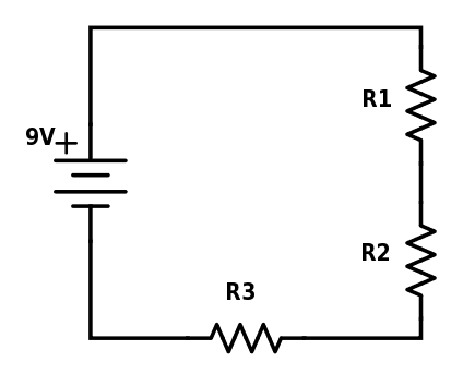
In the image below you have a 9 volt battery connected to three resistor in series. If you measure the voltages over the components – the sum of them will be 9 volts.

How does this help you understand and read circuit diagrams?
Well, often you have components in a circuit that you know have a certain voltage drop.
For example: An LED with a 2V forward voltage will have a 2V voltage drop when it’s lit.
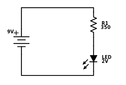
So, if you have such an LED in a circuit with a resistor and 9V battery powers the circuit, you know this:
The resistor will have a voltage drop of 7V (9V minus 2V equals 7V).
Knowing the voltage drop over the resistor let’s you calculate the current through the resistor.
Just use Ohm’s law:
- Current = Voltage / Resistance
- Current = 7V / 350 Ohm
- Current = 0.02A
So, just by knowing Kirchoffs law of voltage, you could find that the current in the circuit is 20mA.
Kirchhoff’s Current Law
Kirchhoff’s current law says: All the current going into a node is equal to all the current that goes out from the node.
A simpler way of saying it is:
“What goes in must come out”
Examples of Kirchhoff’s Current Law
- The current that flows into a circuit must come out from the circuit.
- The current that flows into a resistor must come out of the resistor.
- The current that flows into four resistors in parallel must come out of the four resistors in parallel.
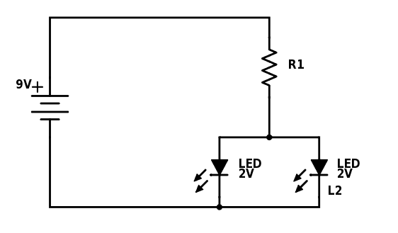
In the circuit above, you can use Kirchoff’s current law to find the current through the components:
What goes in to the resistor R1, must come out of it. And this current has nowhere else to go than into the two branches with the LEDs. And, what goes into the two branches with LEDs must come out of the two branches.
So, you know that the current through the resistor is the same as the total current of the two LEDs.
And as long as the LEDs are of the same type, half of the current will go into the left LED and half into the LED on the right.
Two 2V LEDs in parallel do not affect the voltage drop, which is still 2V. Now you can calculate the current just like we did in the example above with Kirchoff’s voltage law. Then, split the current in half to get the current value for each LED.
When you know this, you can simplify a lot. If you have a big circuit with lots of components in parallel and series mixed, it can be hard to find the individual currents.
But, maybe you don’t need to?
Sometimes it’s good enough to just know that if 500mA goes into this section of the circuit – 500mA will come out of it.
When do you use Kirchhoffs law?
When you understand these laws you rarely use them explicitly. But because you know them, you know how to measure and what results to expect. This means you will use them implicitly all the time when designing circuits, looking at circuits or debugging circuits.
Kirchhoffs laws are really important to get. Learning to design schematics and debugging circuits is so much easier when you understand this law.
Return from Kirchhoffs Law to Electronic Schematics
More Basic Electronics Tutorials
10 Simple Steps to Learn Electronics
Electronics is easy when you know what to focus on and what to ignore. Learn what "the basics" really is and how to learn it fast.

