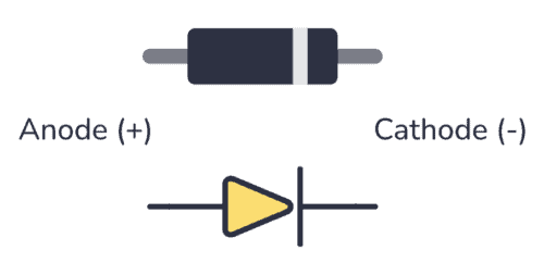
A diode is a component that lets current flow in one direction and blocks it from flowing in the other direction. It has two pins; anode and cathode.
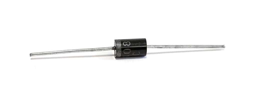
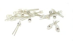
The diode symbol looks like an arrow pointing toward a line. The line represents the cathode side, and so does the line marking on the diode component itself. In the picture above, the line marking is on the left side, so that’s the cathode side.