Understanding Basic Electronics is Easy

Yes, basic electronics is easy. As long as you don’t make it complicated (which many unfortunately do).

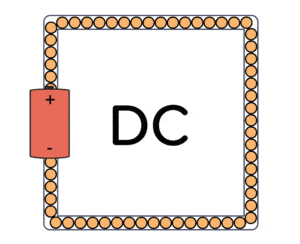
An electrical current is the flow of electrons in a wire. Electrons flow when you have a “closed loop” – a path from the negative to the positive terminal of a battery.

Basic electronics - current flow

For example, if you connect a small light bulb to the positive and the negative side of a battery, you will get a closed loop where electrons can flow and make the lamp shine.

“Electronics” control electrical currents by combining different components.

What is Basic Electronics?

Many think that basic electronics has to do with the physics of how electrons move. But that’s particle physics, not electronics!

You can learn the basics of electronics by learning this:

  • The basics of current and voltage
  • How the most common basic components work
  • How electronic schematics work
  • How to build circuits from schematics
Ohms law cartoon

Voltage Divider Tutorial For Beginners

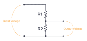
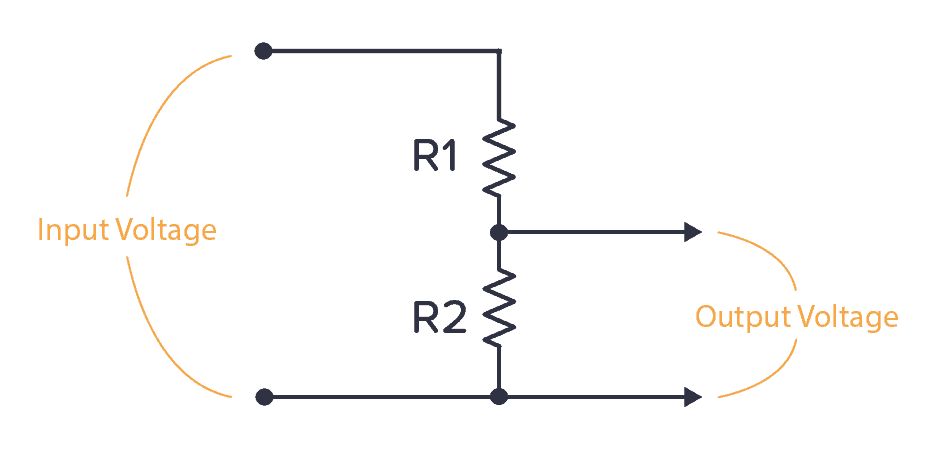
A voltage divider is a circuit that creates a smaller voltage from an input voltage by using two resistors. You’ll see it in both simple and advanced circuits all the time. Here’s the basic setup:

The basic voltage divider circuit

It is useful for example for reading sensors like thermistors and photoresistors since it converts an unknown resistance into a voltage. Or to reduce the volume of an audio signal via a potentiometer.

You can find the output voltage by inserting the resistor values and the input voltage into the following formula:

V_{OUT} = \frac{R2}{R1+R2} \cdot V_{IN}

Or you can use the calculator a little bit further down on this page.

Once you know how it works, it’s much easier to see how circuits work. And it will let you calculate voltages at many different points in a circuit – which is often needed to understand it.

Ohms Law – The Complete Beginner’s Guide

Ohms law is a simple formula that makes it easy to calculate voltage, current, and resistance. You can use it to find what resistor value you need for an LED, how much power your circuit uses, and much more. It’s one of the few formulas in electronics that you’ll use on a regular basis.

Tips: This trick will help you understand circuits

Are you struggling to understand circuits and see how currents flow?

I wrote this based on an interaction I had with Gary.

And maybe it can help you.

I was developing some new material for a course.

And I used Gary as my test subject. He’s an adult British gentleman with no electronics background whatsoever.

He told me that if he could understand this, then anyone could.

Tips: How to combine components?

“How to combine components to get a specific function?”

Many people ask me this.

But that’s like if you want to learn the piano and ask:

“How to combine notes to play a specific song?”

What you need to do to learn to play the piano is to practice playing the piano.

What Is Electric Current?

Electric current is what you get when electric charge moves around a circuit. It’s pretty simple when you finally get it. But there are some common pitfalls that can give you the wrong idea when learning.

And if you don’t know what current is and how it works, it’s a huge source of confusion when learning electronics.

Ohms law cartoon showing that electric current flows.

My goal is that after reading this article, you’ll understand what current is. And you’ll understand that a resistor must have the same amount of current going into it as going out from it.

The RC Delay Element

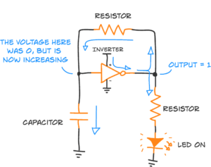
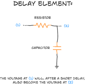
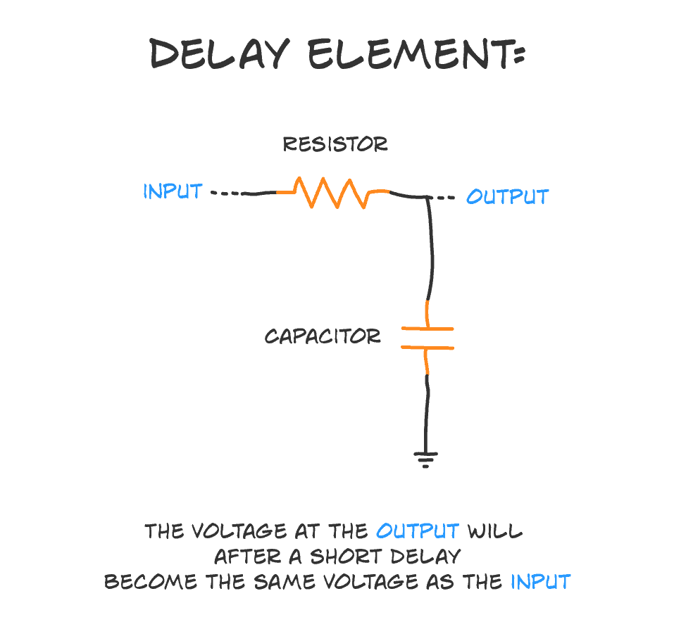
The RC delay element is a way to create a time delay in your circuit by connecting a resistor and a capacitor. It’s super simple. And very useful.

The ‘R’ is a resistor, and the ‘C’ is a capacitor. That’s where the ‘RC’ comes from. And here’s how you connect the two:

RC delay element explanation

Tips: How a circuit simulator can help you understand any circuit

A circuit simulator is a tool for “seeing” what a circuit does. In comparison to mechanical machines such as a bicycle and a lever, electronics cannot be easily inspected by the naked eye.

When you look at a bicycle you can observe it and see that stepping on the pedals makes a chain turn, and that this chain moves the bicycle wheels.

In contrast, if you open up an audio amplifier, it will be really hard to tell what it does if you don’t have previous experience in designing and building electronic circuits.

Kirchhoffs Law of Voltage and Current

Led and a resistor

Kirchhoffs law of current and voltage are two laws that are really useful when you are working with circuits.

Knowing them will make it much easier to understand circuit diagrams, design electronics, repair electronics and everything in between.

Though they might sound complicated (*), they’re not.

After you’ve learned them, it’s not really something you use – it’s something you KNOW. And it makes looking at and understanding circuit diagrams much easier.

What Is A Short Circuit And Why Do You Have It?

A short circuit is a connection that was not meant to be there. For example, if you accidentally connect the plus to the minus of a battery, you have a short circuit between the plus and minus of the battery. Which is not good.
You can use it as a verb as well:

“I accidentally shorted the battery and it exploded!”

(Yes, some batteries can really explode if you short-circuit them.)

This is a very important concept to understand because it’s used a lot in “electronics language”.

What You Need to Know About Current, Voltage and Resistance

Current, voltage and resistance are three important concepts in electronics. I didn’t have a clue about these things when I started out. But I could still build fun things, by following the circuit diagrams I found. I just didn’t know what was going on.

When I started learning about basic electricity in school, many pieces started to fall into place. I started understanding some of the explanations from the circuit diagrams I built.

I like to focus on the practical parts of electronics. But learning some theory as you progress is also really useful. So in today’s article you will learn the basics of current, voltage and resistance.

Series and Parallel Circuits

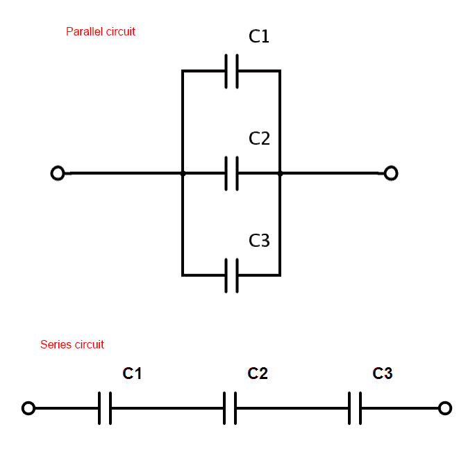
In electronics, we can find both series and parallel circuits.

A series circuit is a circuit where the components are connected in a consecutive chain. This gives the current only one path to take.

A parallel circuit is a circuit where the components are connected parallel to each other. So the current will flow in several paths.

Series and parallel circuits

Often, real circuits have a mix of series and parallel circuits.

Thevenin’s Theorem – A Simple Explanation

Thevenin’s Theorem explains how to simplify a complex circuit. It states that any linear circuit with only voltage sources, current sources, and resistors can be simplified to a voltage source with a series resistor.

But what does this really mean?

Sometimes a picture says more than a thousand words, so here are two pictures to explain what Thevenin’s Theorem is about.