Thevenin’s Theorem explains how to simplify a complex circuit. It states that any linear circuit with only voltage sources, current sources, and resistors can be simplified to a voltage source with a series resistor.
But what does this really mean?
Sometimes a picture says more than a thousand words, so here are two pictures to explain what Thevenin’s Theorem is about.
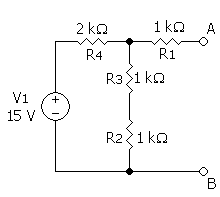
This circuit…
By SteveZodiac [GFDL or CC-BY-SA-3.0], via Wikimedia Commons
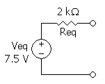
…can be represented by this simple circuit
By SteveZodiac [GFDL or CC-BY-SA-3.0], via Wikimedia Commons
How to use Thevenin’s Theorem
To get from the complex circuit to the simple Thevenin equivalent we:
- Calculate the Thevenin equivalent voltage between terminals A-B open-circuited
- Calculate the Thevenin equivalent resistance between terminals A-B with all current sources open-circuited and all voltage sources short-circuited
Finding the Thevenin Equivalent Voltage
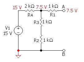
First, we’ll find the equivalent voltage.

10 Simple Steps to Learn Electronics
Electronics is easy when you know what to focus on and what to ignore. Learn what "the basics" really is and how to learn it fast.
By SteveZodiac [GFDL or CC-BY-SA-3.0], via Wikimedia Commons
We see that R4 makes a voltage divider together with R3 and R2. Since R4 = R2 + R3 the voltage will be divided in half on the right side of R4.
Since A is not connected to anything, no current will pass through R1 and therefore no voltage drop will occur over R1. So terminal A is 7.5 V.
Finding the Thevenin Equivalent Resistance
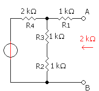
Then, let’s find the equivalent resistance.
By SteveZodiac [GFDL or CC-BY-SA-3.0], via Wikimedia Commons
First, we short-circuit the voltage source. This puts R4 in parallel with R2+R3. We calculate this and get 1k Ohm. This is in series with R1 (also 1k Ohm), so we get an equivalent resistance of 2k Ohms.
Then we put these two together and get the following Thevenin equivalent circuit:
By SteveZodiac [GFDL or CC-BY-SA-3.0], via Wikimedia Commons
What do you use the Thevenin equivalent circuit for?
The Thevenin theorem is really useful for doing calculations with circuits. If you have a complex circuit, you can simplify it and make calculations much easier.
But, I have to admit that I can’t remember ever having applied this outside of a classroom though ;)
More Basic Electronics Tutorials
10 Simple Steps to Learn Electronics
Electronics is easy when you know what to focus on and what to ignore. Learn what "the basics" really is and how to learn it fast.

Dint unstand this….can u plz elaborate it….
This is in (should read “in series”) with R1 (also 1k Ohm), so we get an equivalent resistance of 2k Ohms.
Thanks!
Oyvind
any example for dependent sources will be appreciated.
Hi,olyvind
What is short circuit?
Hi Madhu,
Check out this article:
https://www.build-electronic-circuits.com/short-circuit/
Best,
Oyvind
When short-circuit the voltage source, why didn’t we get R2 in parallel with R4+R3?
Sorry about my English!
Thank you!
This doesn’t make sense. Since there is no voltage potential at A, you have a complete circuit through R2 then R3 and then R4 back to the power source. All of these are in series. So why is it not the sum of all three resisters or 4K ohms?