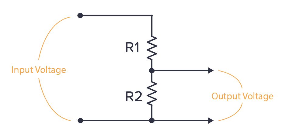
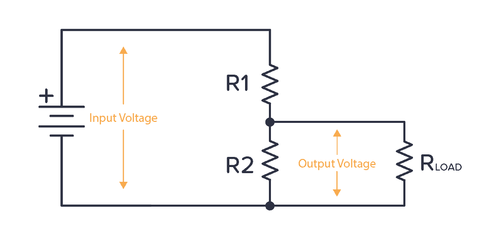
A voltage divider is a circuit that creates a smaller voltage from an input voltage by using two resistors. You’ll see it in both simple and advanced circuits all the time. Here’s the basic setup:
It is useful for example for reading sensors like thermistors and photoresistors since it converts an unknown resistance into a voltage. Or to reduce the volume of an audio signal via a potentiometer.
You can find the output voltage by inserting the resistor values and the input voltage into the following formula:

Or you can use the calculator a little bit further down on this page.
Once you know how it works, it’s much easier to see how circuits work. And it will let you calculate voltages at many different points in a circuit – which is often needed to understand it.
Voltage Divider Formula
This formula is one of the few electronics formulas (in addition to Ohm’s law) that I use on a regular basis.
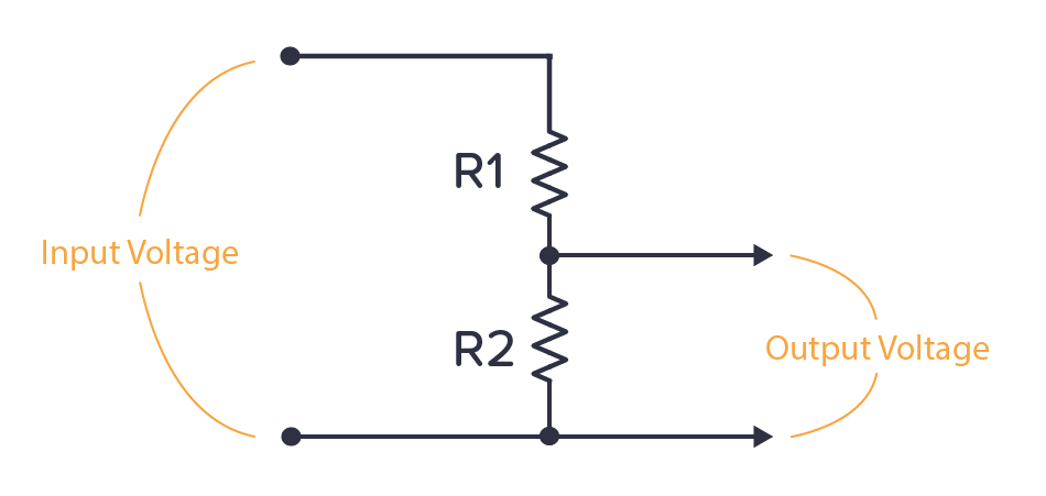
It’s for finding the output voltage when you have two resistors connected like this:

Get Our Basic Electronic Components Guide
Learn how the basic electronic components work so that circuit diagrams will start making sense to you.
The formula for calculating the output voltage is:
This can be a useful formula to remember. It will come in handy often. Or use the voltage divider calculator below if you prefer the easy way ;)
Voltage Divider Calculator
Fill in the input voltage and resistor values in the voltage divider calculator below to find the output voltage:
We’ve added this calculator to a practical voltage divider calculator page that you can bookmark and come back to in the future.
Where Do You Find The Voltage Divider?
One example of a voltage divider circuit is for reading analog sensors.
For example, the thermistor is a temperature sensor. It changes its resistance based on the temperature. If you connect it with a known resistor value in a voltage divider setup, you’ll get a voltage that depends on temperature:
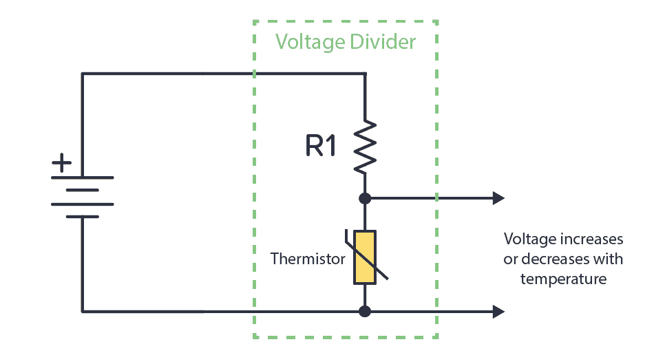
Check out a complete working example in our Arduino Thermistor guide.
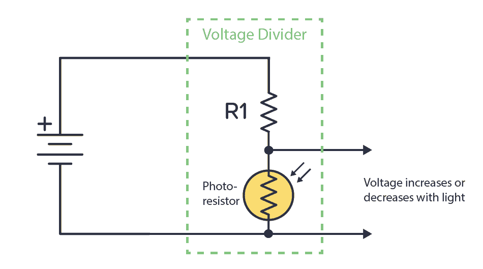
Or you can combine a known resistor with a photoresistor. The photoresistor changes resistance based on the amount of light it detects. This way, you have a circuit that increases or decreases the voltage based on light.
You can connect the output of any of these circuits into a comparator to check it’s above or below a certain voltage. Then do something based on that. For example, if the temperature is above 40 degrees, turn on a fan.
Or connect into an analog pin of an Arduino or a microcontroller and do cool stuff with it. Maybe turn on a light if the photocell indicates that it’s dark?
Calculation Example: Different resistor values
Let’s say we have the following values:


By using the formula above we get

Calculation Example: Equal resistor values
Now, let’s say R1 and R2 has the same value.


By using the formula above we get

This means that when the two resistors have the same value, the output is always half the input.
Can You Use Voltage Divider as a Power Supply?
If you have a circuit that needs 4.5 V, could you use a voltage divider with two 500 Ω resistors to get 4.5 V from your 9V battery?
Unfortunately, it’s not that easy.
Any circuit you want to power will have an internal resistance. So from the perspective of the voltage divider, whatever circuit you connect to the voltage output can be seen as a resistor (RLOAD) connected in parallel with R2.
If the internal resistance of the circuit (RLOAD) is also 500 Ω, what happens?
Now, the R2 from the voltage divider formula becomes the parallel resistance of R2 and RLOAD. Which is just 250 Ω. If you put this into the voltage divider formula, you get an output voltage of 3V instead of the 4.5V you wanted.
For a power supply, you want the voltage to stay at the chosen level no matter if the circuit you connect has a high or low internal resistance. That’s why the voltage divider is not commonly used for power supplies.
Instead, you need to use a voltage regulator.
Questions?
What are your questions about the voltage divider? Let me know in the comment section below.
More Basic Electronics Tutorials

10 Simple Steps to Learn Electronics
Electronics is easy when you know what to focus on and what to ignore. Learn what "the basics" really is and how to learn it fast.
Well, I subscribed, and I enjoy the info attached to the emails, but where is the book???????
Hey Ted
You should have received a link right after signing up. If you can’t find it, just reply to one of my emails and I’ll send you the link again.
Cheers!
Oyvind
thanks for every thing , like learning.
No problem =)
thanks for every think.
I have been wondering about the book that was meant to be sent to me. Given that I live in south africa, was wondering if it got lost in the post.
Hey Delmaine
It’s an ebook. You’ll receive a link for download right after you sign up. If you can’t find the link, just reply to one of the emails and ask for it and I’ll send it again :)
Cheers!
Oyvind
Thank you I like what u are teaching! U are definetly out there!
Thanks Donald, I really appreciate it =)
Oyvind
Your emails are very useful and those inspired me to making circuits.
Cheers
Thanks Thanvir, it means a lot to me to hear that =)
Oyvind
Hey Oyvind, what’s up?
Great article: simple and right to the point.
I would like to ask you a question: suppose I have a circuit that runs on 5V (like Arduino), and I need to add a device that runs on 3V3, that will draw its current from the circuit. Supposing the circuit has enough Ampères to run and supply to the device, is it safe to set up this voltage divider to lower the tension level to 3V3? I am using a breakout from Sparkfun – but two résistors seem to me much cheaper that this breakout… :)
See ya,
Julio
Hey Julio!
Good question =)
Yes, you can use two resistors two go from 5V to 3.3V. But there are some things you need to keep in mind.
Let’s say you put a resistor in parallel with R2, with the same value as R2. The resulting resistance of the parallel connection will be only half the value of R2. And this will reduce the output voltage from the voltage divider.
If you want to power a circuit with the output from the voltage divider, you have to make sure that R2 in the voltage divider is much much lower than the resistance from 3.3V to ground in the circuit you want to power. (And this resistance might vary depending on what it going on in the circuit, so you can’t simply measure it)
You might be tempted to think that you can just use extremely small resistors for R1 and R2. But the problem with this is that then you would need extremely high precision on your resistors to get the right voltage.
Basically it all comes down to the circuit you want to power. So I recommend you to test it out and observe what happens. It might work. It might be too unstable.
Oyvind
THANKS FOR YOUR TEACHING. THEY ARE SO WELL PUT. THAT IS A GIFT. THEY ARE ENJOYABLE ALSO.
COULD YOU SEND ME THE LINK TO YOUR EBOOK I AM ALSO FROM SOUTH AFRICA.
THANKING YOU ONCE AGAIN
REGARDS
COLIN
You get the link automatically when you confirm your newsletter subscription. If you can’t find it, reply to your welcome email and I’ll help you.
Oyvind
hi
who can i get ldr
Hello Oyvind,
My name is Jason, I’m from England & asked for an Arduino for Christmas. I’ve been going through the starter kit guide. I understand all the code, logic and what the components do, but the explanations in how the schematics work together is limited. I have been trying to figure out why a resistive photo cell needs to use a voltage divider when it is already a resistor. But after watching and reading the info on your site I think I have it. A resistor by itself just limits the current, whereas a voltage divider lowers the voltage. This is more useful as the arduino main thing is reading voltage levels.
Is this right or am I still missing so information?
Thanks,
Jason
Hey Jason,
You seem to have figured it out yourself =)
The Arduino reads voltage level, so we need a voltage divider to convert the changing resistance of the LDR into changing a voltage level.
Keep up the good work!
Oyvind
hey Øyvind
whats up ?
i am mahfuj and i am from Bangladesh. i want to design a 7 segment binary decoder for my class project what are the elements needed for the project.
please help me
Can I ask u one doublt….it is very well told that the voltage divider circuit cannot be used for connecting any load. Then what is the real use of dividing voltage since the current is same throughout the circuit.
Please forgive me if the question is a blunder.
Can u please include a bit of stuff relating to the transformers. Am seeing 3 pin, 4pin, etc transformers, making a lot of confusions, some of which having 6 to 8 pins soldered to the board.
Hey Anurag, good question!
You don’t use a voltage divider as a power source. Because once you introduce more resistors – like a load – then the voltage will change.
But you willl see voltage dividers in many circuits. For example, do you see the voltage divider in this ligh-sensor circuit: https://www.build-electronic-circuits.com/ldr-circuit-diagram
For transformers – look up the datasheet to sort out the pins.
Cheers!
Oyvind
Hi Øyvind,
I have a power source (12V Battery), but the rating can vary 5 AH / 7 AH / 9 AH. The device to be used needs to provided with 12 V (DC) and would like to limit the current to 3 amps or 4 amps for experimentation to understand the outcome at various power levels.
Can you suggest me how to limit the current using resistors.
Hey,
The battery rating you refer to only tells you the capacity of the battery. 5AH means the battery *could* give 5A for 1 hour. Or 1A for 5 hours.
To control the current with a resistance is easy – just use ohm’s law.
V = I * R
or
R = V / I
So if you have 12V and want 1A you get:
R = 12 / 1 = 12 Ohm
Just connect the voltage source to the 12 ohm resistor, and you’ll have 1A running through it.
If you’re connected some device, the device itself will control the current as long as you provide the correct voltage.
Best,
Oyvind
Hello sir, i have a question.
I added a 100ohm resister between the middle input pin and ground pin of a volume potentiometer because i wanted to reduce the sudden volume increase caused by low quality pot. It works well. But
I want to ask. Does it mean it will drain the batteries of my radio fast, because isn’t it kind of short circuiting the input volume to ground?.
Plz replt. Thanks.
I will calculate if there are 3 series of connected resistors or more
Combine two of them into one. The total resistance of two resistors in series is the sum of the two.
This is good man .completely useful
Great article on voltage divider, I’m curious when it comes to using resisters and choosing the correct ones. I.e Say I want to go from 5v down 2.5v I could use 220ohm for R1 & R2, or I could
use 10k ohm for R1 & R2, how do you know which way to go in terms of lower or higher ohms?
Thanks! Often, it doesn’t matter as long as it’s not too small (which will give a lot of current) or too high (which will give very little current).
But note that the voltage divider will not work as a power supply. I just added another section above called “Can You Use Voltage Divider as a Power Supply?” that describes why (in case that’s what you were thinking about).
Dear Oyvind,
I am a mechanical engineer and very new to electronics. I have already made pulse charger to charge batteries but now I need to automate it.
Say I have the power source and a mosfet bank in between and the battery. The mosfets are driven by a frequency Generator say at 200Hz and the current flowing is controlled by the PW of the Freq Gen.
Now I do this manually and I need to use a Arduino +
ACS712 module 30A Hall Current Sensor in series prior to mosfet bank and thru the voltage signal of current sensor I want to alter the PW out of the Arduino in order to achieve the set point current, say 8 Amps. I want to fit and forget so that the Arduino UNO runs auto pumping constant set point curent by the way of altering the pulse width.
Can you help me in this.
I am struggling with the Arduino coding for this.
Please Help
Hey Samantha,
Have a look for the AnalogWrite command. That’s what decides the pulse width. Usually it’s a value between 0 (0% pw) and 255 (100% pw).
Best,
Oyvind
Thank you for the great instructional material! Regarding the voltage divider, everything above makes sense to me except the calculation for trying to get 4.5V from a 9V battery using 2, 500 ohm resistors. If R load is 500 ohms, then the parallel resistance between R2 and R load is 250 ohms. So, to get the output voltage from the voltage divider we now have R1/(R1+R2)(9V)=500/(500+250)(9V)=6V, not the 3V as written. Do I have something wrong here?
Hey Woody, you switched R1 and R2. R2 should be on top: 9V * R2/(R1+R2)
Ok, got it. Thank you!
What value of resistor R1 with 3pin IR receiver instead of photodiode? IR output is 0.7 volt. When comparator, I would like to do R1 voltage lower than IR receiver. I am biginner. Please answer.
It’s a bit hard to understand what you’re trying to do. If you can specify the IR receiver model number, that might help.
how can you do voltage divider if there is more than two resistors and loads and if loads are connected in complex manner
You need to combine resistors in series and parallel and calculate their combine resistance.
Thank you very much. I appreciate it.
I want to ask some questions.
Hi. I am Pierre-Andre. I have a question about the amount of current in the different paths of the voltage divider. let say we have an input of 10V and R1 = 500 ohms; the max current through this resistor will be 10V/500 ohms= 0,02A right? Now, let say that the load is a simple LED connevcted to the junction of R1 and R2 and the junction of R2 and Neg side of the input; since the voltage at the LED will be more than enough to switch ON the LED, the current will be able to flow without (or with very little) restriction through the LED (right?). Will there be any current flowing through R2 since it can fly through the LED? If so, how do we calculate that? Thanks a lot, your explanations are very good.