This LDR circuit diagram shows how you can make a light detector. An LDR or “Light Dependent Resistor” is a resistor where the resistance decreases with the strength of the light.
Here is the schematic for the circuit:
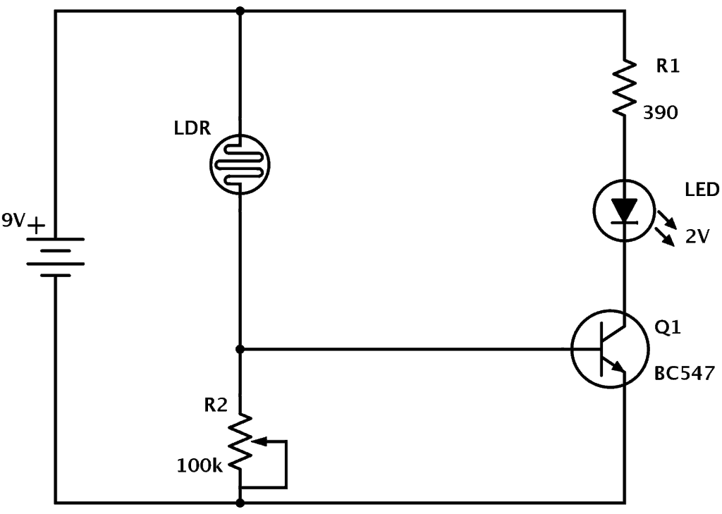

This LDR circuit diagram shows how you can make a light detector. An LDR or “Light Dependent Resistor” is a resistor where the resistance decreases with the strength of the light.
Here is the schematic for the circuit:
Recently I have been using this free circuit drawing software from Digikey. It’s called SchemeIt.
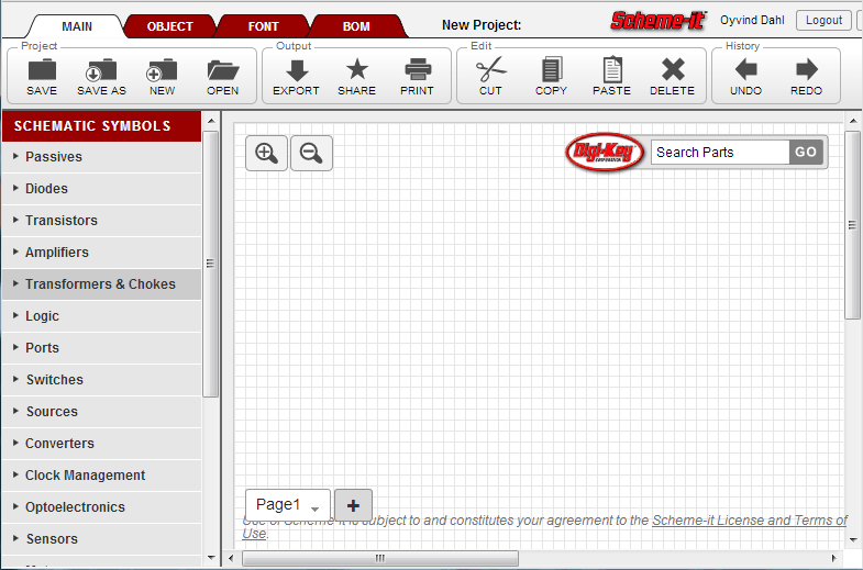
If you need a simple and fast way to draw a schematic diagram, it’s the best. It’s browser-based so you don’t have to download anything.
You don’t have to register. But if you want you can register and save your designs.
When you design a circuit board, you need to follow the PCB design rules of your manufacturer. These rules are the limits of the machine that makes the circuit boards.
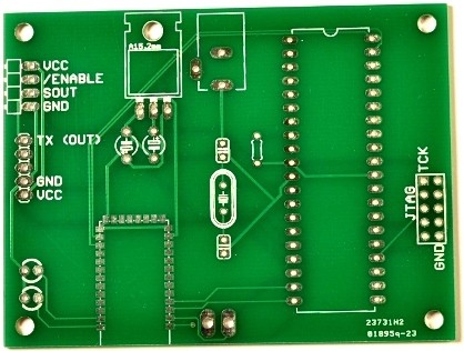
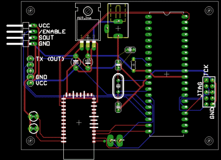
The first time I looked at the rules I got really bummed out because it seemed so freakin’ complicated.
“Why can’t they just make my PCB???”
After a while I calmed down and had a look at what I was up against. And it wasn’t that bad after all ;)
6 steps for how to build a circuit:
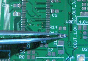
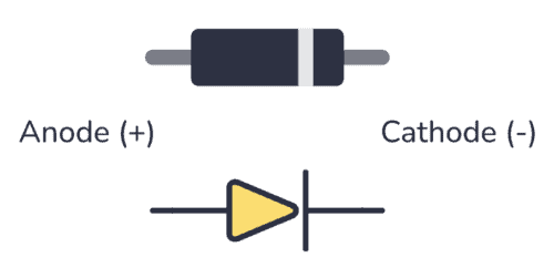
A diode is a component that only conducts electricity in one direction. It is commonly used to convert from alternating current (AC) to direct current (DC).
Several types of diodes exist. And it can be a bit confusing if you have never worked with diodes before.
I would like to share the most standard types of diodes that are commonly used by hobbyists.
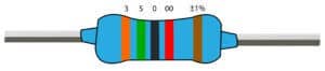
A current limiting resistor is a resistor that is used to reduce the current in a circuit.
A simple example is a resistor in series with an LED.
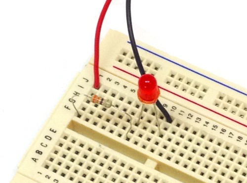
You would usually want to have a current limiting resistor in series with your LED so that you can control the amount of current through the LED.
If too much current is going through your LED, it will burn out too fast. If too little current is going through it, it might not be enough to lit the LED.
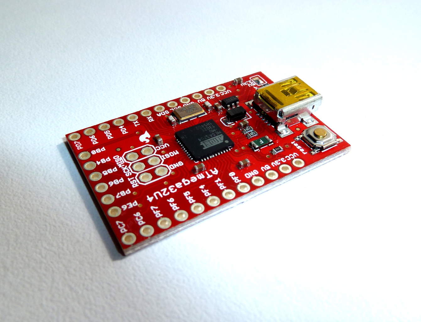 Using a microcontroller board is a simple way to get started using microcontrollers in your projects. You will get a development board with a microcontroller and all the components needed to make it work.
This means you can focus on your idea instead of the details around setting up a microcontroller circuit.
And usually the schematic diagram is provided so that you can easily incorporate the microcontroller in your own circuit later on.
I often use a microcontroller board when I want to test a new microcontroller. Or when I want to make a prototype.
I wanted to write a little bit about some of the boards I have used.

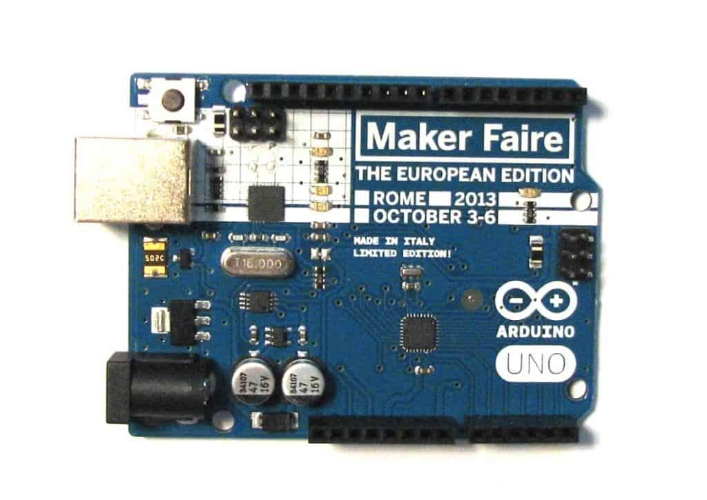
If you haven’t started Arduino programming yet, it’s about time. The Arduino is a microcontroller board originally made for Interaction Design students in Italy. It was specifically developed to make it easy to start programming microcontrollers – even if you have no technical background.
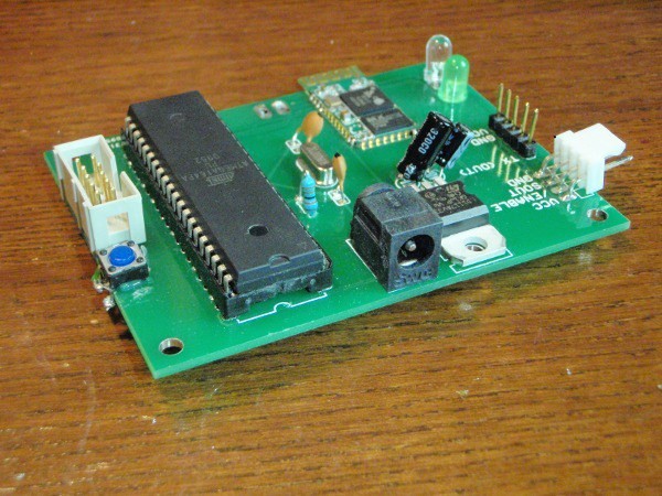
I loved learning about the microcontroller basics when I was studying. It meant I could start taking advantage of microcontrollers in my electronics projects. It kind of felt like with this knowledge, I was unstoppable. I could build ANYTHING!
And it is actually true. Microcontrollers are powerful components. They let you write programs to control your electronics. Combine this knowledge with how to build your own circuit boards, and you’re gonna make amazing things.
By using a microcontroller in your project you will have access to a vast amount of functionality from the tips of your (programming) fingers.
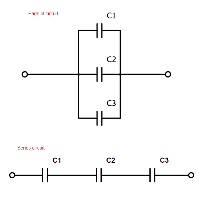
In electronics, we can find both series and parallel circuits.
A series circuit is a circuit where the components are connected in a consecutive chain. This gives the current only one path to take.
A parallel circuit is a circuit where the components are connected parallel to each other. So the current will flow in several paths.
Often, real circuits have a mix of series and parallel circuits.
Thevenin’s Theorem explains how to simplify a complex circuit. It states that any linear circuit with only voltage sources, current sources, and resistors can be simplified to a voltage source with a series resistor.
Sometimes a picture says more than a thousand words, so here are two pictures to explain what Thevenin’s Theorem is about.
This is a timer project I recently made.
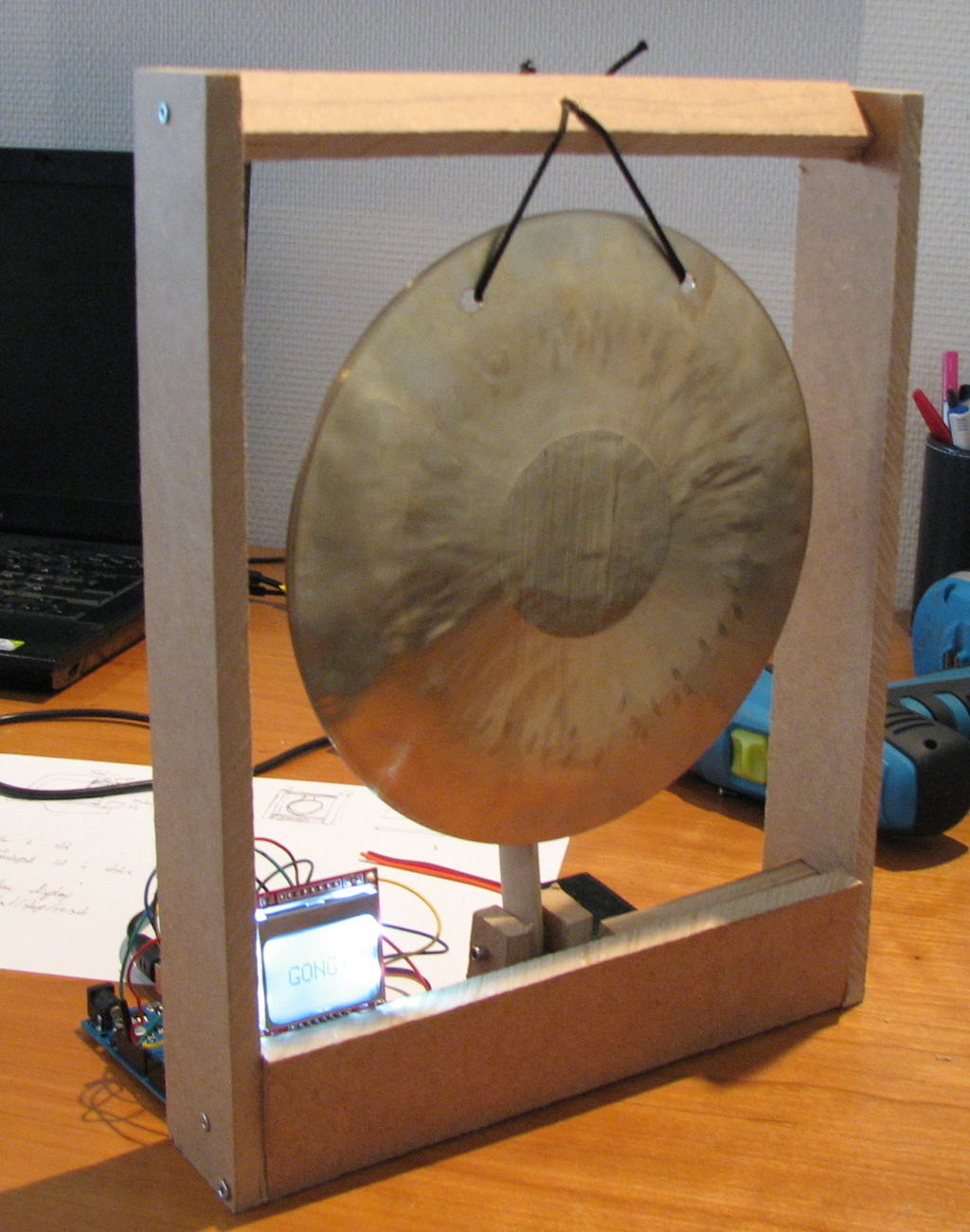
I am really into productivity techniques and I think using the Pomodoro technique is a nice way of working when you need to be productive.
You work hard for 25 minutes, then take a 5 minute break.
Also, I have found that the sound of a gong makes me really relaxed and focused. So I decided to build a timer project with a gong.
I wanted the gong to “gong” at the start to make me focus, then “gong” at the end to make me relax during the break.

This is an electronics project of mine. It’s a 1937 Philips radio modified into a docking station.
The reason I did it was because I had this old Philips radio laying around. And I couldn’t use it because it only had an AM receiver. So, I thought it would be cool to make it into an iPhone dock =D
The first thing I did was to remove old the old parts from it.
In this Arduino shield tutorial, I will show you how to create a 4×4 LED matrix Arduino shield. You can make any shield you want using this method.
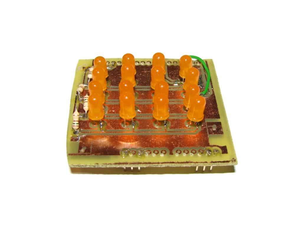
The tutorial consists of three videos:
I have been looking for a good stereo amplifier circuit diagram for a long time. I am not a HiFi geek, I just wanted to build a simple stereo amplifier that could drive some speakers for my desktop computer.
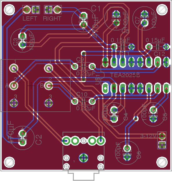
All the schematic diagrams that I could find seemed to involve lots of hard-to-find components or you had to use it together with a pre-amplifier or some other amplifier stage. It was always something that made me hesitate.
But recently I found this awesome little chip called TEA2025! You only need a few capacitors to make a decent stereo amplifier out of it. It is so simple to build that I put it together on a stripboard in just a few hours.