In this guide, you’ll learn how to control an RGB LED using the Arduino. An RGB (Red-Green-Blue) LED can produce a wide variety of colors by mixing different intensities of red, green, and blue light. You’ll learn to create a basic Arduino RGB LED circuit and cycle through some basic colors as an example.
Using the provided schematic and breadboard images, as well as the example code below, you should have everything you need to easily set up and control an RGB LED’s color output on your own.
Parts Needed
- Arduino Uno
- Breadboard (and some breadboard wires)
- 3 x Resistor (220 Ω)
- RGB LED
There are two types of RGB LEDs: Common Anode and Common Cathode. We’ll provide example schematics and code for both types below.
How To Connect an RGB LED to an Arduino
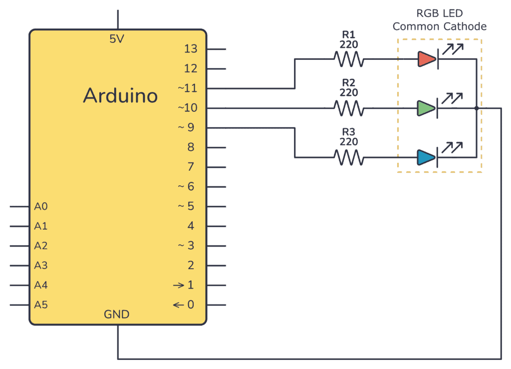
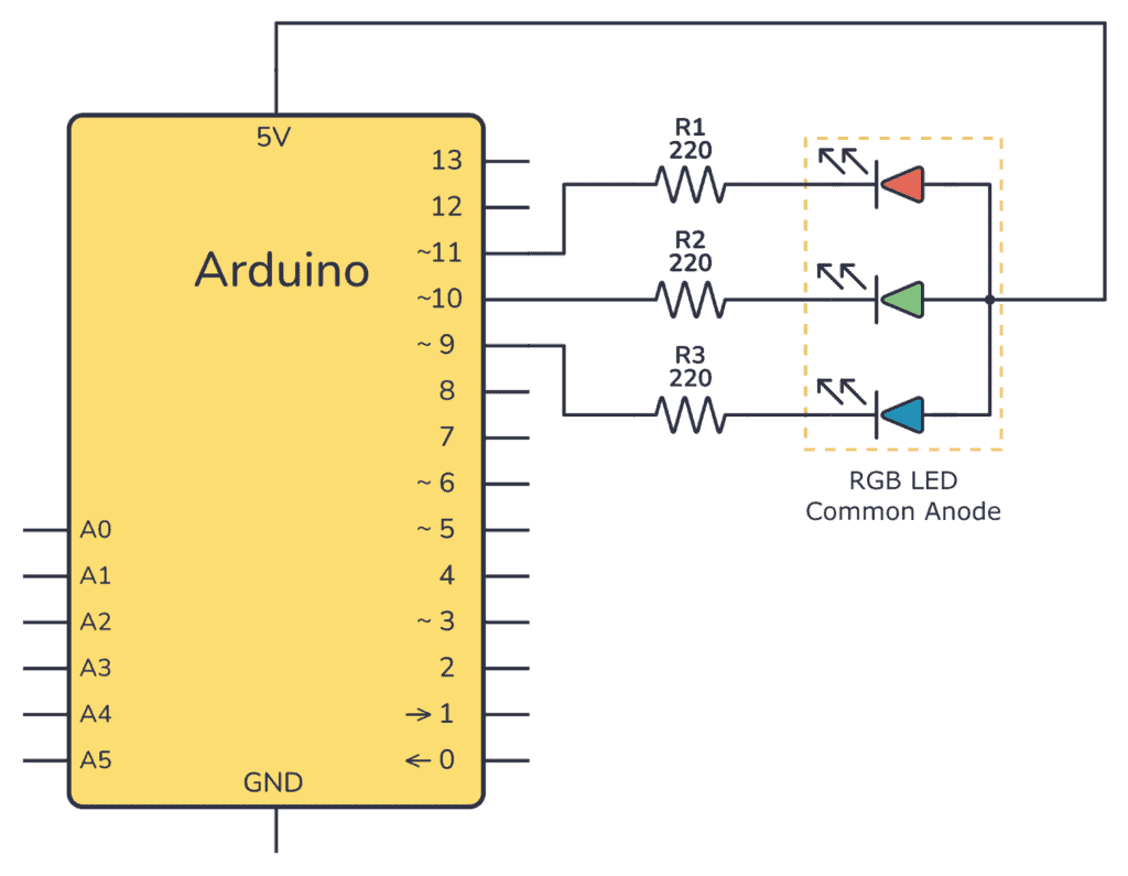
Here’s the schematic for the circuit. This diagram uses three resistors and a common anode RGB LED (you’ll find the schematics for a common cathode below).
If you’re using a common anode LED, you need to connect the common anode pin to 5V, like this:
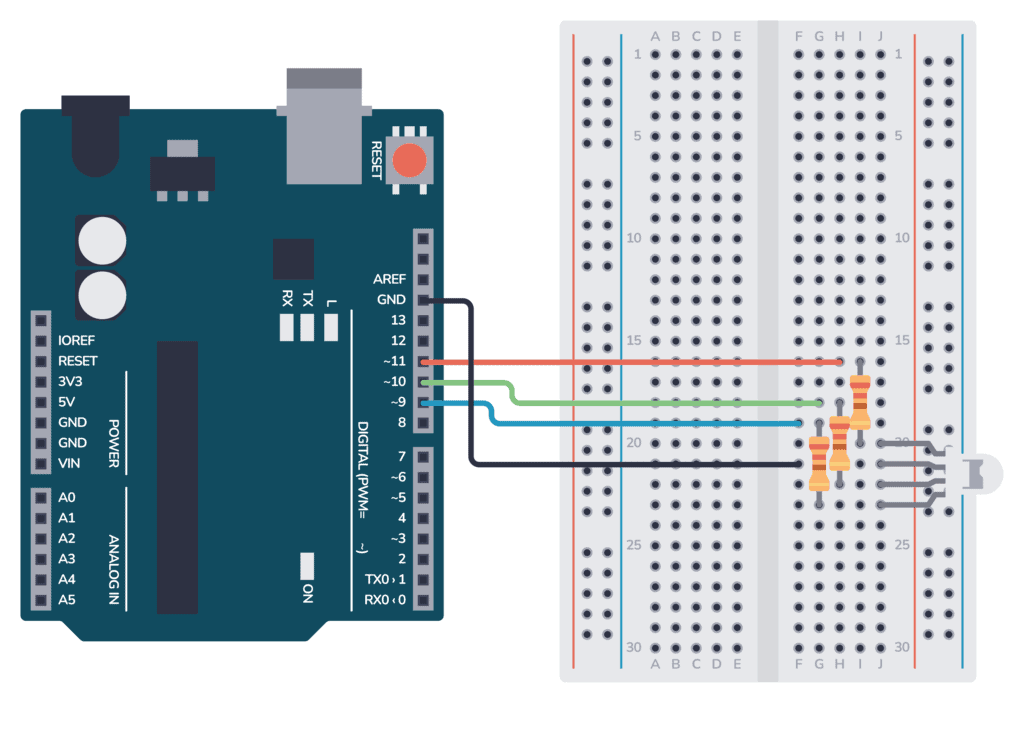
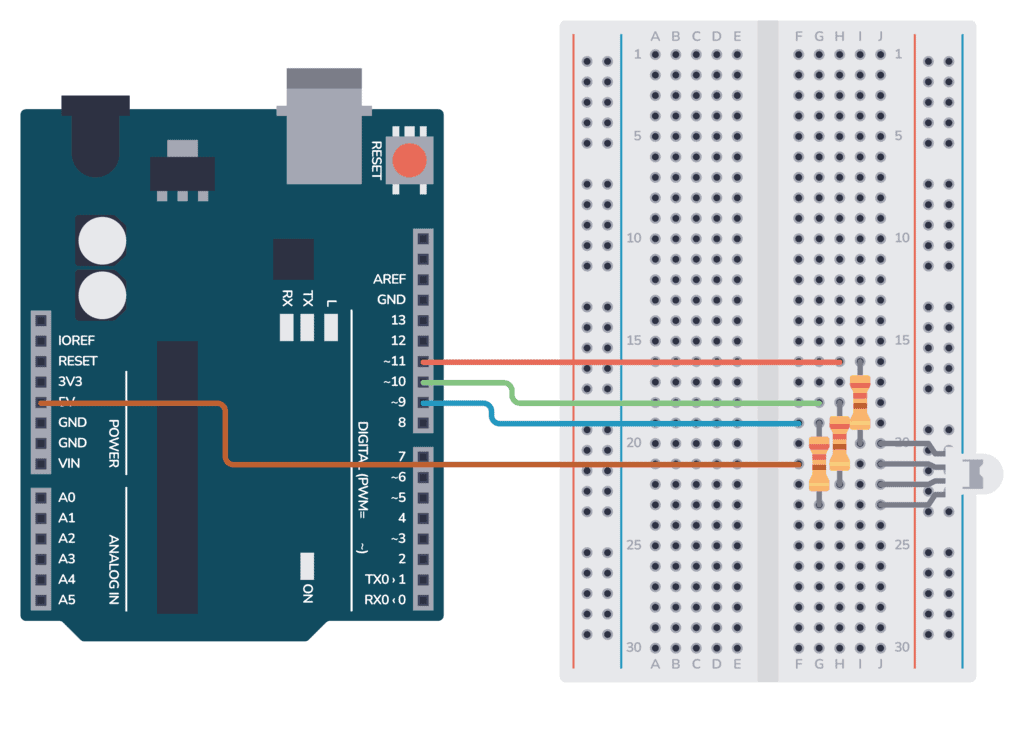
Steps To Connect the Circuit on a Breadboard
- If you’re using a common cathode RGB LED, connect the cathode to the GND pin on the Arduino. If your RGB LED is a common anode, connect the anode to the 5V pin on the Arduino.
- Connect the red, green, and blue legs of the LED to pins 11, 10, and 9 of the Arduino respectively, each through a 220-ohm resistor.
- Make sure your Arduino is connected to your computer via a USB cable.
Use one of the breadboard images below as a visual guide to set up your connections:
Upload the Arduino RGB LED Code
Upload the code below to your Arduino using the Arduino IDE, and you should see the LED cycle through different colors, stopping for one second on each color.
Complete Arduino code for RGB LED (Common Cathode):
Basic Electronics for Arduino Makers
Learn the basics that every Arduino maker should know, and it'll open you up to a world of possibilities! Sign up for my circuit tips by email and I'll send you the eBook:
int redPin= 11;
int greenPin = 10;
int bluePin = 9;

void setup() {
  pinMode(redPin, OUTPUT);
  pinMode(greenPin, OUTPUT);
  pinMode(bluePin, OUTPUT);
}

void loop() {
  setColor(255, 0, 0); // Red Color
  delay(1000);

  setColor(0, 255, 0); // Green Color
  delay(1000);

  setColor(0, 0, 255); // Blue Color
  delay(1000);

  setColor(255, 255, 0); // Yellow Color
  delay(1000);

  setColor(0, 255, 255); // Cyan Color
  delay(1000);

  setColor(255, 0, 255); // Magenta Color
  delay(1000);

  setColor(255, 165, 0); // Orange Color
  delay(1000);

  setColor(128, 0, 128); // Purple Color
  delay(1000);

  setColor(255, 255, 255); // White Color
  delay(1000);
}

void setColor(int redValue, int greenValue, int blueValue) {
  analogWrite(redPin, redValue);
  analogWrite(greenPin, greenValue);
  analogWrite(bluePin, blueValue);
}
If you’re using a common anode RGB LED, the logic is inverted compared to a common cathode RGB LED. In a common cathode RGB LED, you provide power (HIGH) to a specific pin to turn on a color. For a common anode RGB LED, you ground (LOW) a specific pin to turn on a color.
So, for a common anode RGB LED, to set the color, you need to subtract each color value from the maximum (which is 255) before applying it. This inversion ensures that a value of 255 (full intensity) for a specific color results in that color being turned off, while a value of 0 (no intensity) results in that color being fully on.
Complete Arduino code for RGB LED (Common Anode):
int redPin= 11;
int greenPin = 10;
int bluePin = 9;

void setup() {
  pinMode(redPin, OUTPUT);
  pinMode(greenPin, OUTPUT);
  pinMode(bluePin, OUTPUT);
}

void loop() {
  setColor(255, 0, 0); // Red Color
  delay(1000);

  setColor(0, 255, 0); // Green Color
  delay(1000);

  setColor(0, 0, 255); // Blue Color
  delay(1000);

  setColor(255, 255, 0); // Yellow Color
  delay(1000);

  setColor(0, 255, 255); // Cyan Color
  delay(1000);

  setColor(255, 0, 255); // Magenta Color
  delay(1000);

  setColor(255, 165, 0); // Orange Color
  delay(1000);

  setColor(128, 0, 128); // Purple Color
  delay(1000);

  setColor(255, 255, 255); // White Color
  delay(1000);
}

void setColor(int redValue, int greenValue, int blueValue) {
  analogWrite(redPin, 255 - redValue);
  analogWrite(greenPin, 255 - greenValue);
  analogWrite(bluePin, 255 - blueValue);
}
How the Code Works
This code first sets up the RGB-led pins via the variables redPin, greenPin, and bluePin. Change these if you are using different pins than in the example circuit.
Then, the code lights up the RGB LED with the colors red, green, blue, yellow, cyan, magenta, orange, purple, and white, pausing for a second on each color.
Conclusion
Enjoy experimenting with different color combinations by altering the values in the setColor function! Remember, RGB LEDs combine red, green, and blue light to produce a vast array of colors. You’re now equipped to create colorful displays with your Arduino and RGB LED!
More Arduino Tutorials
Basic Electronics for Arduino Makers
Learn the basics that every Arduino maker should know, and it'll open you up to a world of possibilities! Sign up for my circuit tips by email and I'll send you the eBook: