This Arduino Light sensor circuit is a simple example that shows you how to connect light sensors such as photoresistors, photodiodes, and phototransistors, to an Arduino.
In this quickstart guide, you’ll learn how to connect a photoresistor to an Arduino board and read out the voltage. You’ll first use the Serial Monitor to learn about how the light sensor behaves, then you build a circuit that automatically turns on a light when it gets dark.
This is a great practice circuit when you’re learning Arduino. The code is straightforward and the light sensor connections are simple.
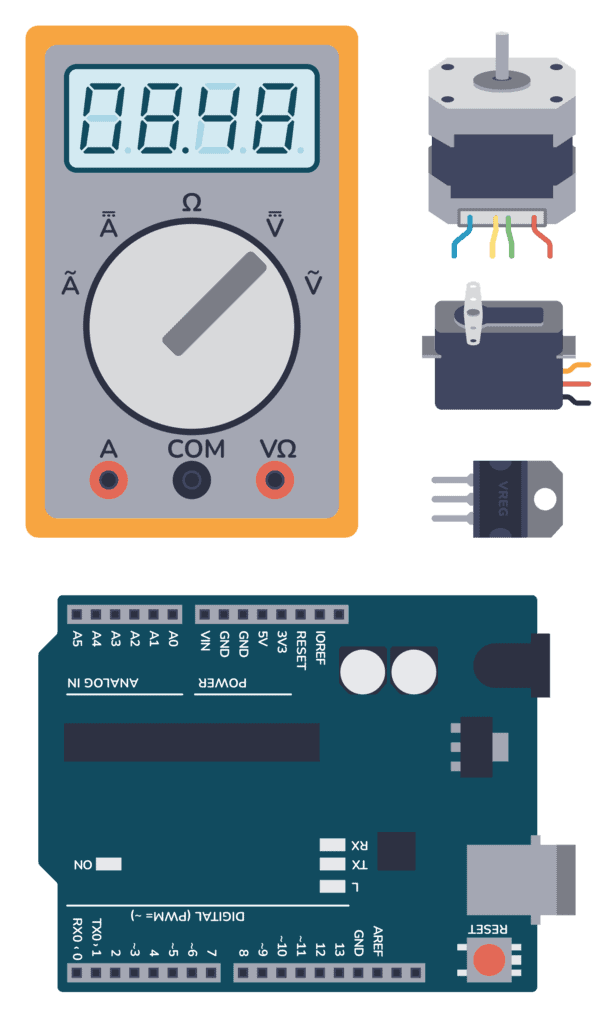
Parts Needed
- Arduino Uno
- Breadboard (and some breadboard wires)
- Photoresistor – also called Light Dependent Resistor (LDR) *
- Resistor 10 kΩ
- Wires
* A photodiode or phototransistor will also work.
Connecting a Light Sensor to an Arduino
To connect a light sensor to an Arduino, connect the light sensor in series with a resistor between 5V and GND. Then connect the middle point between the resistor and light sensor to an analog input pin on the Arduino.
This setup works with photoresistors, photodiodes, and phototransistors.

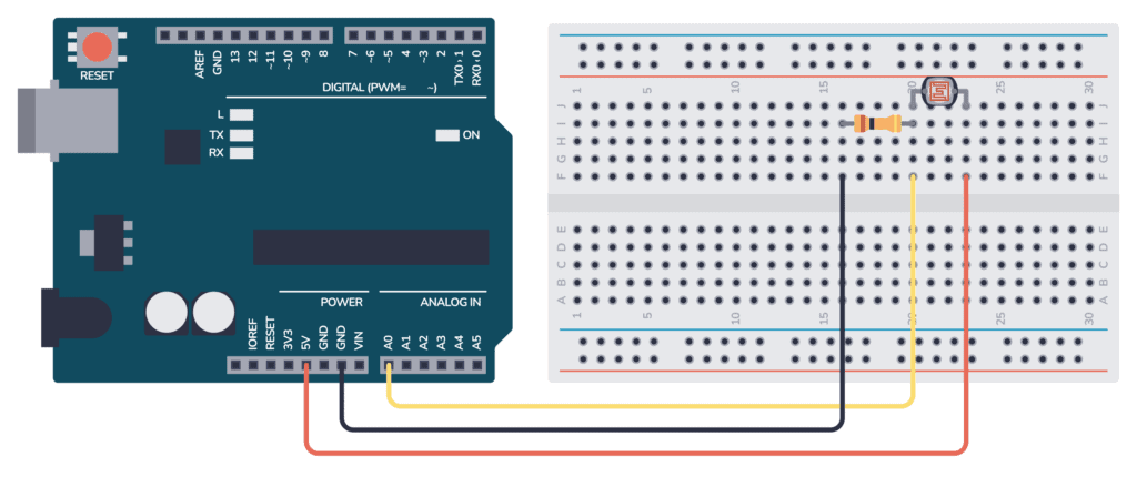
Connecting the Arduino Light Sensor on a Breadboard
Here’s how you can connect this circuit to an Arduino by using a breadboard and some cables:
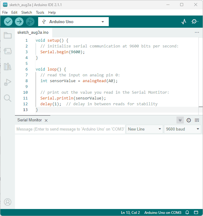
Arduino Light Sensor Code
This Arduino code is an example of reading the voltage from the light sensor (connected to analog pin A0) and then printing the value of the analog reading to the Serial Monitor.
Basic Electronics for Arduino Makers
Learn the basics that every Arduino maker should know, and it'll open you up to a world of possibilities! Sign up for my circuit tips by email and I'll send you the eBook:
There’s also some code that will try to determine if it’s dark, dim, light, bright, or very bright. You’ll have to tweak the thresholds in order for it to work with your sensor.
An analog pin will give you a value between 0 and 1023, where 0 means 0V and 1023 means the maximum voltage possible (usually 5V).
As with all Arduino code, you have the two main functions setup() and loop():
- Inside setup(), you need to configure the Serial port so that you can read out values.
- Inside loop(), you need to read the analog input and print this value out on the Serial port.
void setup() {
  // Setup serial communication at baudrate 9600 for reading the light sensor
  Serial.begin(9600);
}

void loop() {
  // reads the input on analog pin A0
  int lightValue = analogRead(A0);

  // Print out the values to read in the Serial Monitor
  Serial.print("Analog reading (0-1023): ");
  Serial.print(lightValue);

  // Use the value to determine how dark it is
  // (Try tweaking these to make it more accurate)
  if (lightValue < 10) {
    Serial.println(" - Dark");
  } else if (lightValue < 200) {
    Serial.println(" - Dim");
  } else if (lightValue < 500) {
    Serial.println(" - Light");
  } else if (lightValue < 800) {
    Serial.println(" - Bright");
  } else {
    Serial.println(" - Very bright");
  }

  delay(500);
}
How the Code Works
Inside the setup() function there is only one line: Serial.begin(9600); This line sets up the serial port of the Arduino so that it’s possible to send data out from the Arduino and into your computer.
Inside the loop() function there are four sections:
int lightValue= analogRead(A0);: This line reads the analog voltage present at analog pin A0. It returns a value between 0 and 1023, representing the voltage level on the pin relative to the reference voltage (usually 5V for most Arduino boards). The value is stored in the variablelightValue.Serial.println(lightValue);: This line prints the value of lightValue to the Serial Monitor so you can read it.if (lightValue < 10) { ...These lines will use predetermined thresholds to determine if it’s dark, dim, light, bright, or very bright. You’ll have to tweak the thresholds to make them work for your sensor.delay(500);: This line adds a small delay of 500 milliseconds between each reading and printing. This delay prevents the code from running too quickly. This way it’s easier to read the readings on the Serial Monitor.
The end result of this code is that it continuously reads the analog voltage at pin A0, prints the reading (a number between 0 and 1023) and a brightness value (dark, dim, light, bright, or very bright) to the Serial Monitor, and repeats the process in a loop.
When you put your hand over the sensor, the amount of light it detects will change, and you can observe the changing values in the Serial Monitor. This is a helpful way to visualize the data and debug when things aren’t working as expected.
Using The Serial Monitor
To use the Serial Monitor to check the results from the code above, follow these steps:
- Connect your Arduino board to your computer using a USB cable.
- Upload the provided code to your Arduino board using the Arduino IDE.
- Open the Serial Monitor by clicking the magnifying glass icon or using the keyboard shortcut
Ctrl + Shift + M(Windows/Linux) orCmd + Shift + M(Mac). - Set the baud rate in the Serial Monitor to 9600 (or the same value as in the
Serial.begin()function in the code). - Read the output in the Serial Monitor.
- Place your hand over the light sensor to see how the readings change in real-time.
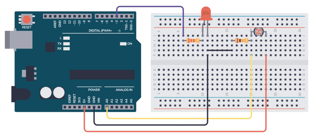
Example: Dark-Activated LED
Here’s an example circuit where a Light-Emitting Diode (LED) is turned on when it gets dark. You could easily replace the LED with something more powerful if you want to control an outdoor light. You can learn more about how to do that in our transistor tutorial.
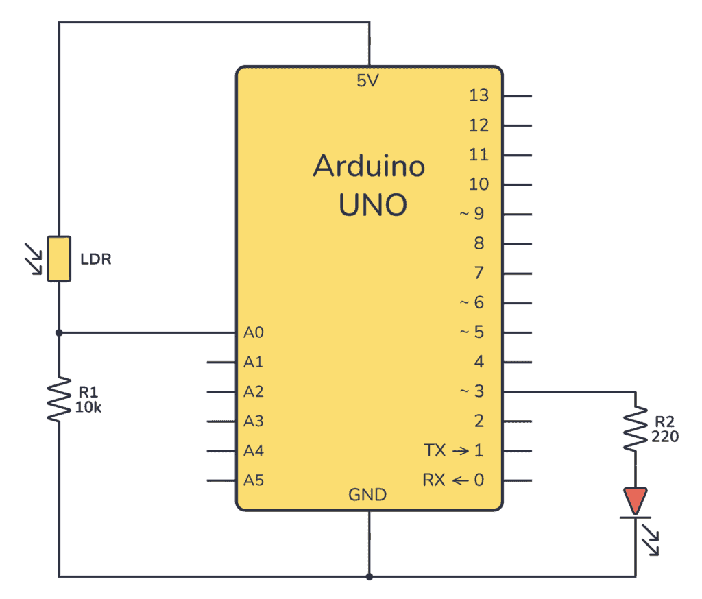
Here’s how to connect the circuit on a breadboard:
The Code
// Definition of constants - values that will never change
const int LIGHT_SENSOR = A0;
const int LED          = 3;

// Definition of variables - values that can change
int analogValue;

void setup() {
  // Set the LED pin as an output
  pinMode(LED, OUTPUT);
}

void loop() {
  // read the input from the analog pin
  analogValue = analogRead(LIGHT_SENSOR);

  // Check if it's above a specific threshold and turn the LED on or off
  if(analogValue < 700)
    digitalWrite(LED, HIGH); // turn on LED
  else
    digitalWrite(LED, LOW);  // turn off LED
}
More Arduino Tutorials
Basic Electronics for Arduino Makers
Learn the basics that every Arduino maker should know, and it'll open you up to a world of possibilities! Sign up for my circuit tips by email and I'll send you the eBook: