In this guide, I’ll show you how to build a DIY sugar dispenser using parts made of cardboard.
By making the parts out of cardboard, it’s quick and easy to build and experiment with different ways to have your machine dispense sugar.
When you’ve built a cardboard-based sugar dispenser that you’re happy with, you can consider upgrading it by building the mechanics using other more durable materials (ex laser cutting plastic).
But for now, let’s build our cardboard prototype!
Sugar Dispenser Circuit
In the following image, you can find the schematics of the circuit you are going to connect.
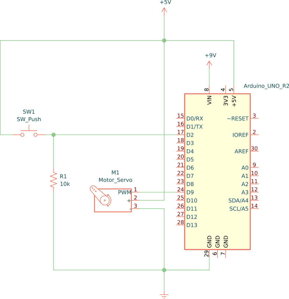
The button and the servo motor are the two primary parts of the circuit. The button part will allow you to control the amount of sugar in a cup.
The servo motor has three pins; 5V, GND, and PWM. You need to connect the PWM pin to an Arduino pin that can output PWM signals, such as D9.
Making a box for the sugar dispenser is the most difficult part of this project. You may create it the way I did below, or use your own design. Either way, you’ll put your engineering skills to the test =)

Build Something Useful This Evening
This gadget lets you use any IR remote-control to control your lamp, garden lights, heater oven, garage door, or anything else.
Necessary Components
- Arduino Uno
- Micro Servo Motor
- Button
- 10kΩ resistor
- Blank perfboard
- Jumper wires
- 2 x cardboard boxes
- Pin header socket with four pins
- Elastic band
- 9V battery or adapter for Arduino powering
Necessary Tools
- Soldering Iron
- Hot glue gun
How It Works
The servo motor opens or closes the sugar dispenser using a little piece of cardboard that moves over a hole.
The servo motor is controlled by the Arduino and will open the sugar dispenser whenever you push the button. When you release the button, the Arduino moves the servo back and closes the hole.
Building The Circuit
We’ll start by soldering the button, the resistor, and the pin header on a perfboard. Then we’ll connect the servo and power supply. And finally, we’ll upload the code.
Creating the Button Board
In this step, you are going to make a button that you will use to control the amount of sugar.
Take a blank perfboard and solder a button to it.
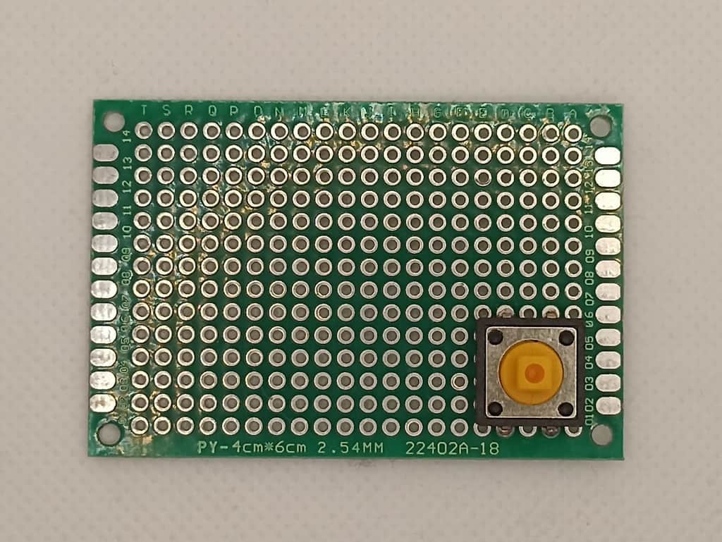
Take the pin header socket and solder it beside the button. You can use either male or female, you just need the opposite version for your jumper wires:
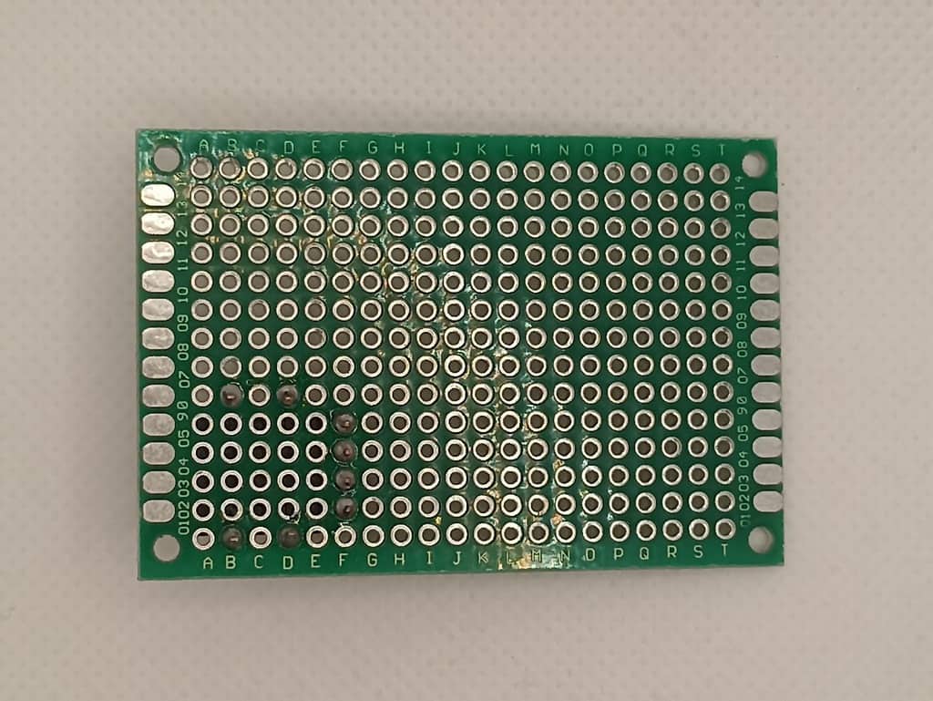
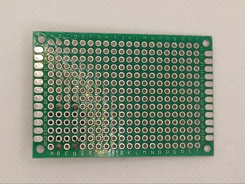
Solder the closest pin of the socket with the closest pin of the button. This will be connected to the Arduino in a later step:
Next, solder the upper button pin with pins 2 and 3 on the socket. On this pin, you will connect the Vcc (5V) in a later step.
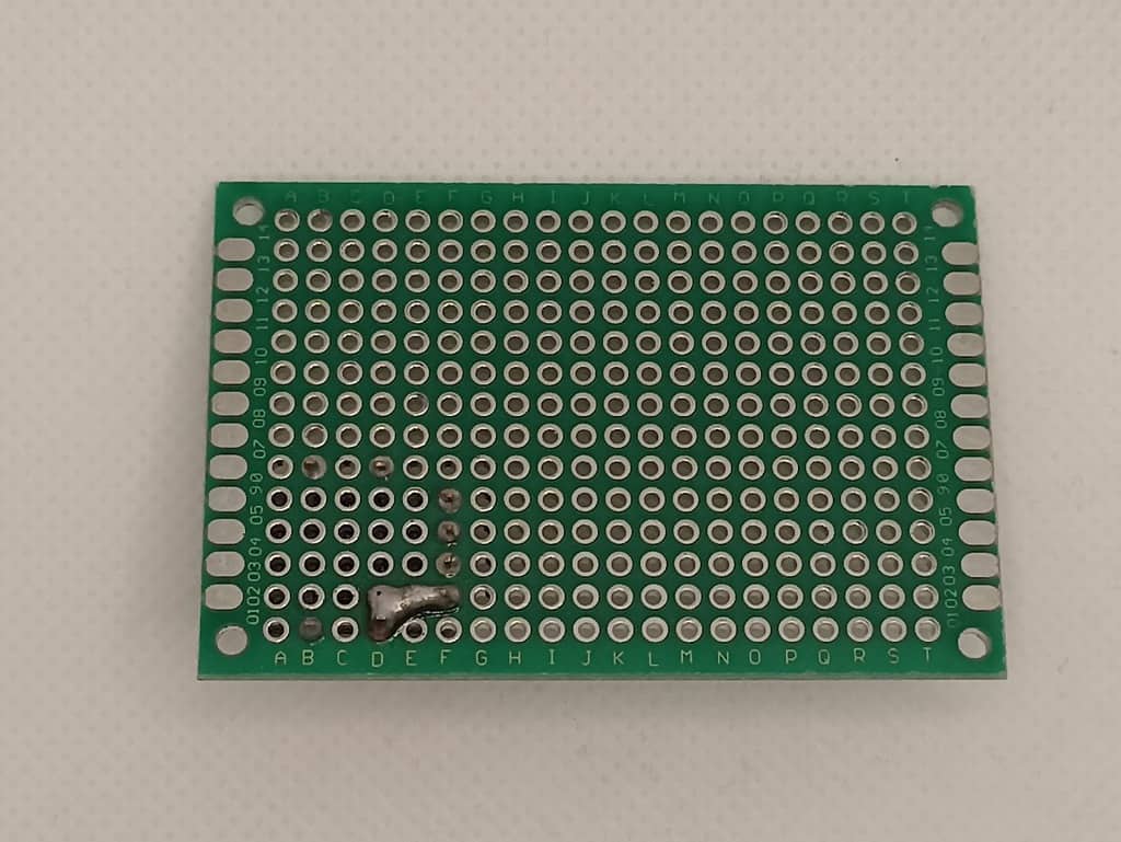
Take your resistor and solder it to the PCB:
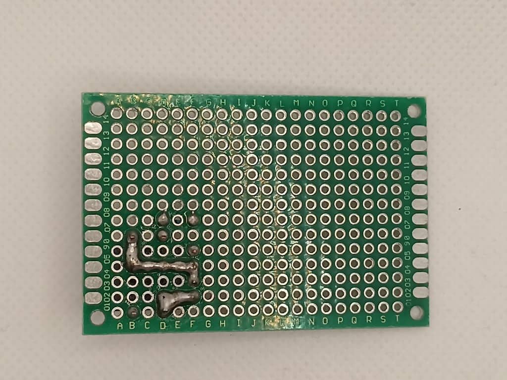
Solder one pin of the resistor to a free pin of the button. And the second leg of the resistor to the remaining pin of the socket. This will be the GND pin.
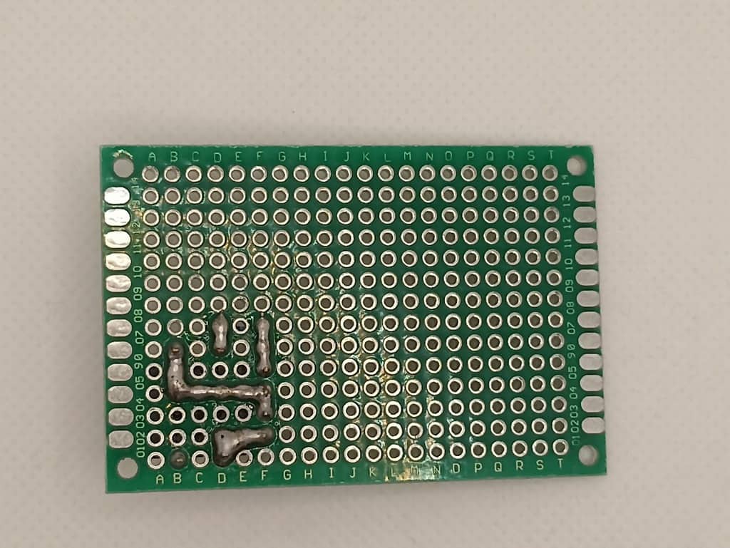
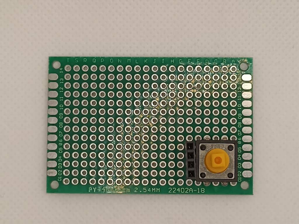
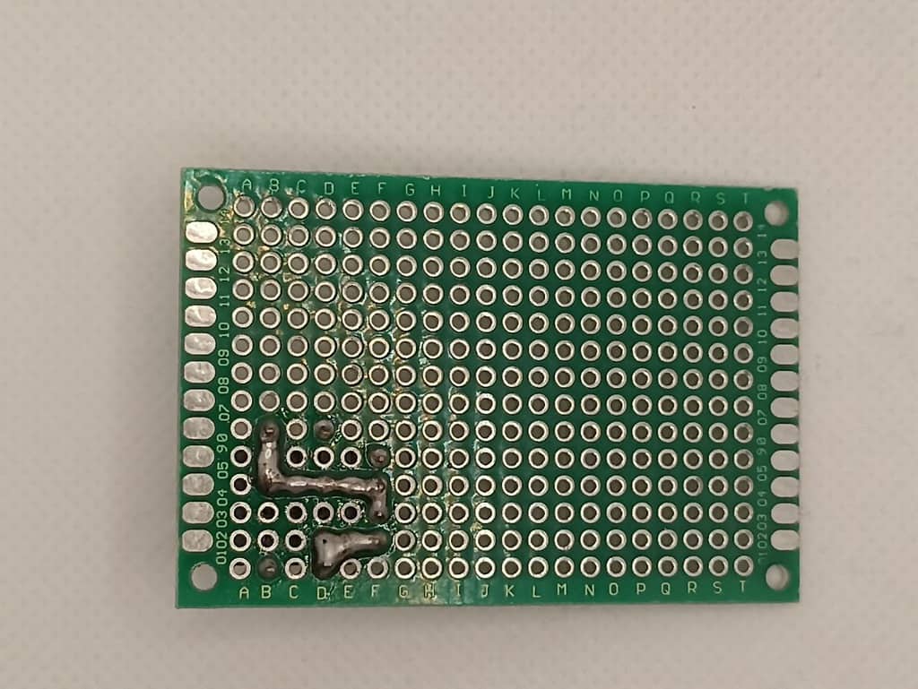
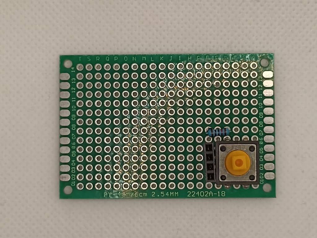
You have your button ready for the machine!
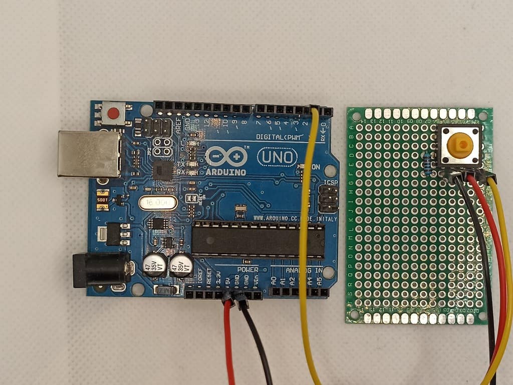
Next, connect everything to the Arduino. Take your Arduino Uno and the board you just made and make the following connections:
- Connect the rightmost header pin on your button board (PWM) with pin 2 on the Arduino
- Connect the third pin from the right (5V) to 5V on the Arduino
- Connect the fourth pin from the right (GND) to the GND on the Arduino
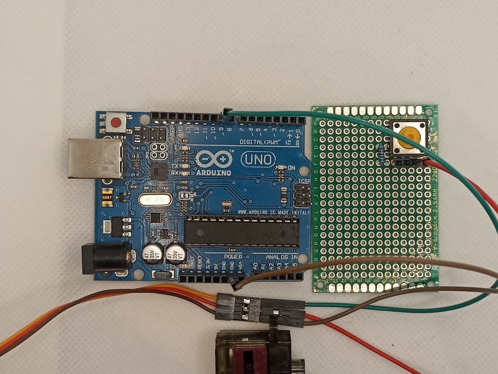
Connecting the Servo Motor
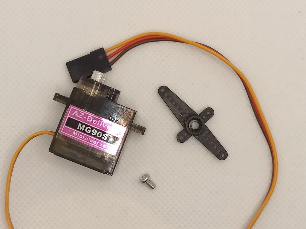
The highlight of this project is the Servo Motor. It is a small, light server motor with high output power. The servo can spin around 180 degrees (90 in each direction). It comes with three wires: power, ground, and signal.
Just for simplicity, the connections made in the previous step are removed from the following image, but you shouldn’t remove anything. Make the following connections:
- The signal wire (orange) of the servo motor connects to pin 9 of the Arduino
- The power wire (red) of the servo motor connects to the remaining pin of the header socket on your button board
- GND wire (brown) of the servo motor connects to the GND on the Arduino
In the following image, we can see the whole circuit connected together:
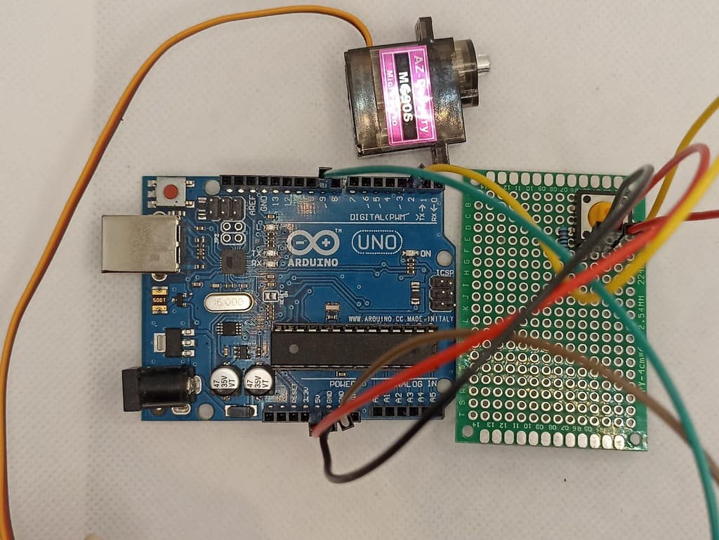
There is one remaining thing left for the circuit part to be finished, and that’s powering of Arduino. You can use a battery that you will connect to the Vin pin of the Arduino, or an adapter, in this case, I used an adapter.
Code
Copy and paste the following code into your Arduino IDE. Compile and upload it to your Arduino. When uploading code to the Arduino, don’t forget to disconnect the power to the Arduino as it will be powered through the cable connected to your computer instead.
Note: you need to include the Servo library in the code
#include <Servo.h> //including servo library
int button = 2; //button pin
int press = 0; //variable to check if the button is pressed
int previous = 0; //variable to check the previous state of the button
Servo servo;

void setup()
{
  pinMode(button, INPUT); //setting button as the input
  servo.attach(9); //pin for servo control signal
}

void loop()
{
  press = digitalRead(button); //putting the state of the button into "press" variable, if it is pressed "press" variable will have value 1, otherwise 0
  if (press == HIGH) //checking if the button is pressed
  {
    if (!previous) { //checking if the button was not pressed in the previous state
      servo.write(80); //if the button was not pressed, then will rotate servo motor
    }
    previous = 1; //setting "previous" value to 1 because the button is pressed
  }
  else{ //case when the button is not pressed
    if (previous) { //if the button in the previous step was pressed and not pressed anymore
      servo.write(30); //rotating servo back
    }
    previous = 0; //setting "previous" value to 0 because button was not pressed
  }
  delay(200); //short delay
}
Making The Machine
This, I believe, is the most difficult stage in the project, and it is here that we will put our engineering skills to the test. This was my approach to and solution to the problem; if you have a better idea, please feel free to do it differently.
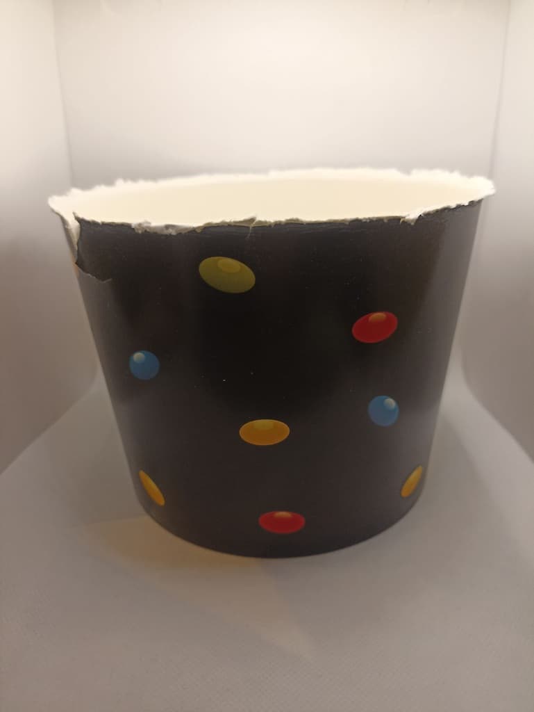
Start with using some box and use a hot glue gun to glue some flat cardboard on the top of the box.
In the next step glue the servo motor to the edge of the box, and make sure you screw the horn (arm) to it before:
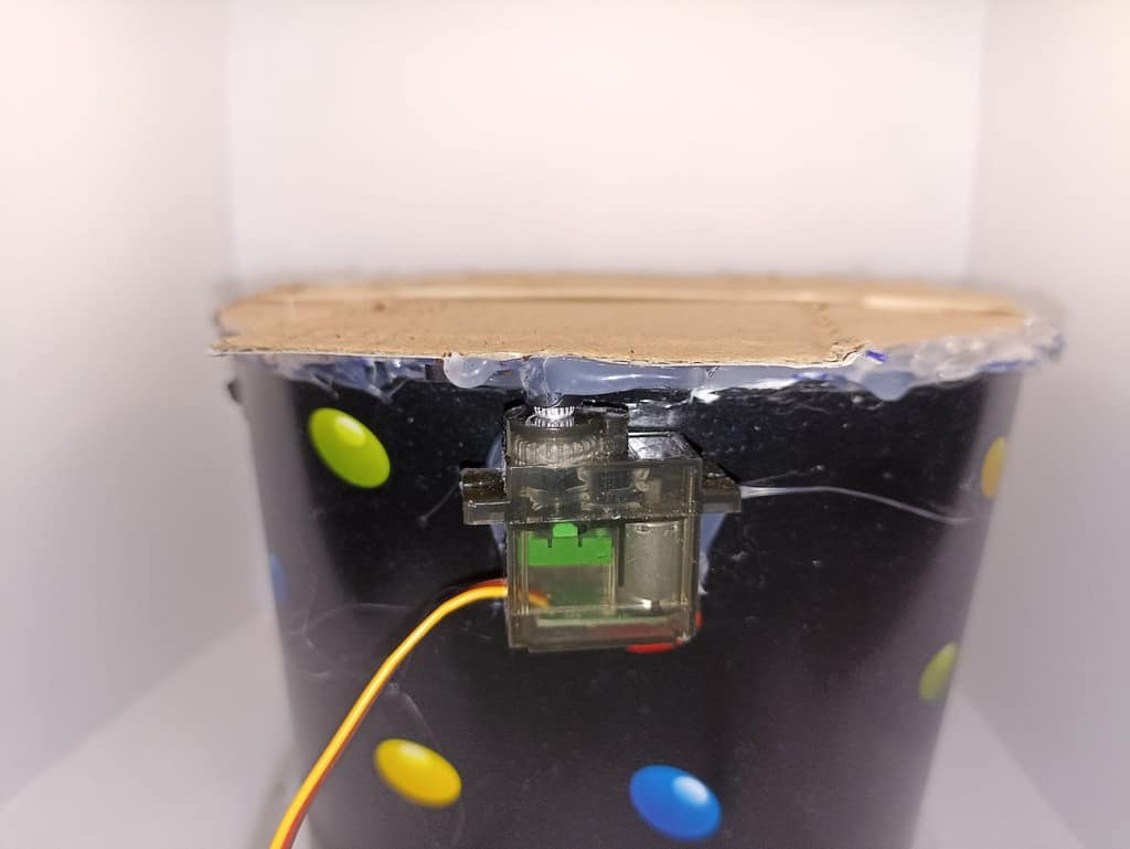
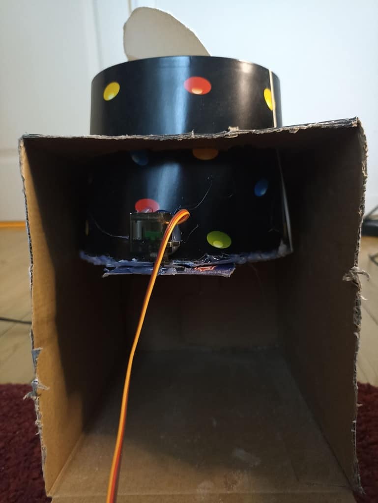
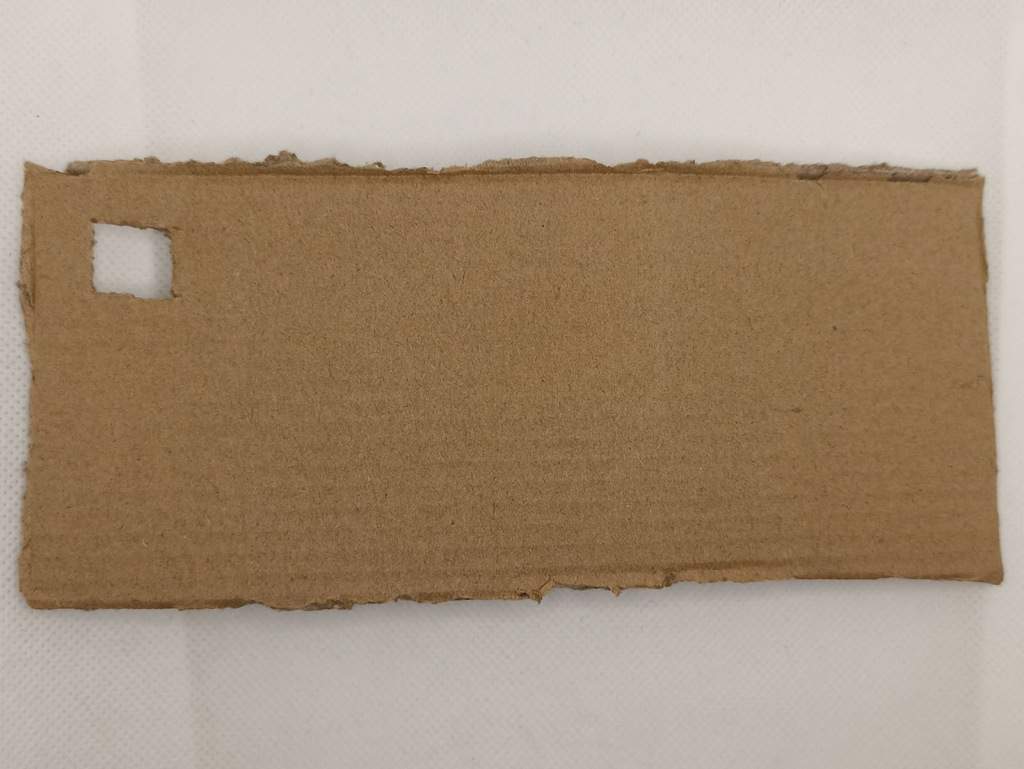
Make a small hole on the cardboard for the sugar to flow through. Then take another piece of the cardboard, rectangular shape, with the end of it glued to the arm of the servo. You can secure it more using an elastic band.
It should be connected in such a way that the servo can move it to cover or uncover the hole below. Check out the following video to see how this part should work:
Now take the greater box, on top of it cut the circle shape, and insert the box you already made up to half. It should look like this:
You could have a functional dispenser right here, but I wanted to make it more professional looking for my kitchen, so I took the extra rectangular cardboard, make a square hole size for the button on it, and on the other side of that cardboard place your Arduino and PCB with the button.
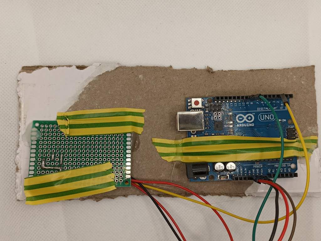
In this step, you should insert the power for Arduino, either battery or adapter, and once again use a hot glue gun to glue this part to the box.
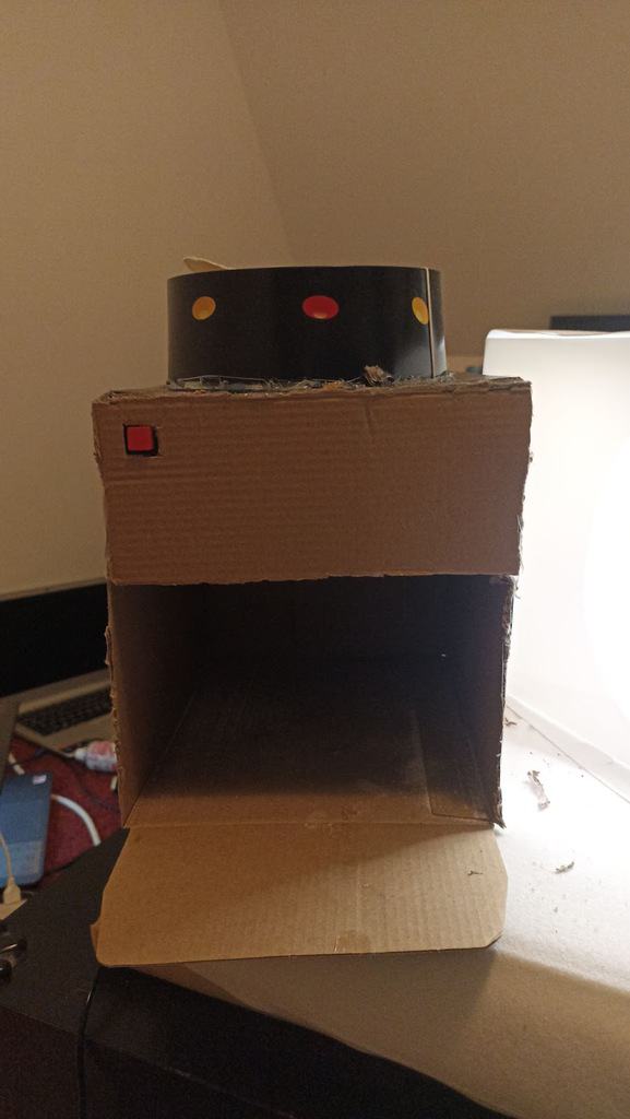
And that is the last step, put something in the box (ex. sugar, rice, oats..), place a mug under, press the button, and enjoy!
The Result
More Circuits & Projects Tutorials
Build Something Useful This Evening
This gadget lets you use any IR remote-control to control your lamp, garden lights, heater oven, garage door, or anything else.