 In this tutorial, I’ll show you how to create a color-changing lamp with Intel Galileo.
You’ll convert from a temperature to a color on an RGB LED. You can also build this project with an Arduino, pretty much the same way.
If you’re new to this board, check out how to get started with Intel Galileo.
Shopping List:
Step 1: Test the RGB LED
Connect the RGB LED onto a breadboard. Connect the common pin to 5V. Add a 330 Ohm resistor from each of the color pins, and use jumper wires to connect the three of them to pin 9, 10 and 11 on the Galileo.
I used three 330 Ohm resistors, but the voltage drop of the three light-emitting diodes are not equal. Mine had a 2V diode for the red, and 3.2V diodes for the green and blue. Which means that in a perfect world, you should have a different resistors value for the red pin. But it works fine with 330 on all of them.
You can learn how to calculate resistor values here.

10 Simple Steps to Learn Electronics
Electronics is easy when you know what to focus on and what to ignore. Learn what "the basics" really is and how to learn it fast.
Then test to see if all the colors are working. Upload the following code to test the different colors:
const int red_pin = 11;
const int green_pin = 10;
const int blue_pin = 9;

void setup() {
  pinMode(green_pin, OUTPUT);
  pinMode(blue_pin, OUTPUT);
  pinMode(red_pin, OUTPUT);
}


void loop() {
  //Red
  setColor(255, 0, 0);
  delay(1000);

  //Green
  setColor(0, 255, 0);
  delay(1000);

  //Blue
  setColor(0, 0, 255);
  delay(1000);

  //Pink
  setColor(255, 0, 255);
  delay(1000);

  //Turquoise
  setColor(0, 255, 255);
  delay(1000);

  //Yellow
  setColor(255, 255, 0);
  delay(1000);

  //White
  setColor(255, 255, 255);
  delay(1000);

}

//Custom made method for setting the color
void setColor(int red, int green, int blue)
{
  analogWrite(red_pin, 255 - red);
  analogWrite(green_pin, 255 - green);
  analogWrite(blue_pin, 255 - blue);
}
This should make your Intel Galileo change the color of the RGB LED like this:
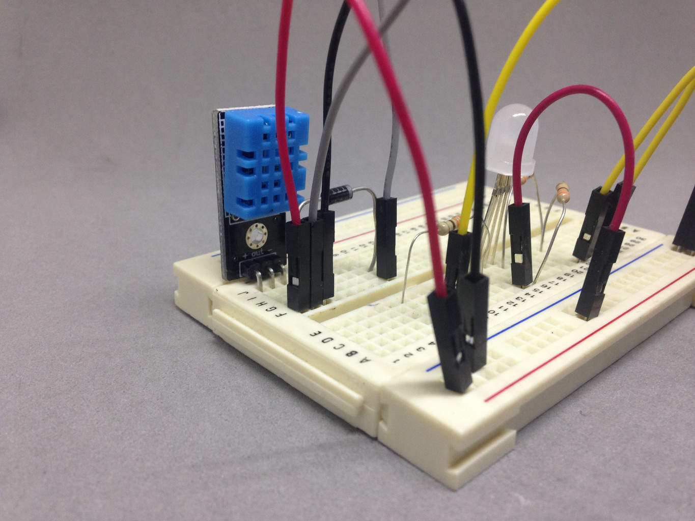
Step 2: Connect the temperature sensor
The DHT11 sensor is pretty straightforward. But it uses a one-wire interface that causes a problem for the Intel Galileo. The problem is that the one-wire interface requires one pin to be switched back and forth between being an input and an output.
On an Arduino this happens really fast and is no problem. But on the Galileo this switching is too slow. Therefore, we need to use a diode to divide the data pin into an input and an output pin. Like this:
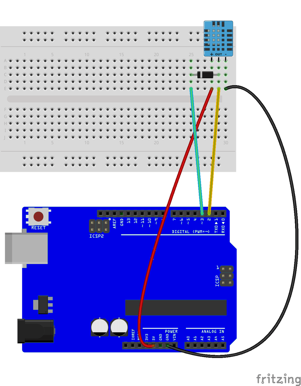
Note: Different modules have different pin placements. On mine, the data pin is on the middle pin. On others, it’s on the left or right.
Because of the modification above, you need a modified version of the DHT library: DHT library for Intel Galileo (Code by adafruit, modified by Dino Tinitigan)
Learn how to add custom libraries to Arduino.
Step 3: Create code for the Intel Galileo
Now, all you need to do is to create the final code. The code needs to:
- Read the temperature
- Convert this temperature into a color
- Display the color on the RGB LED
Below is the code I created (based on the example code from the DHT library):
#include "DHT.h"

// what pins we're connected to
#define DHTIN 2
#define DHTOUT 3
// Define the type (DHT11)
#define DHTTYPE DHT11

DHT dht(DHTIN,DHTOUT, DHTTYPE);

const int red_pin = 11;
const int green_pin = 10;
const int blue_pin = 9;

void setup() {
  Serial.begin(9600);

  pinMode(green_pin, OUTPUT);
  pinMode(blue_pin, OUTPUT);
  pinMode(red_pin, OUTPUT);

  //Initialize the sensor
  dht.begin();
}

void loop() {

  // Read temperature as Celsius and convert from float to int
  int temp = (int)dht.readTemperature();

  // Check if any reads failed and try again.
  if (isnan(temp)) {
    Serial.println("Failed to read from DHT sensor!");
  }
  else {
    Serial.print("Temperature: ");
    Serial.println(temp);

    // Set temperature range
    int high_temp = 35;
    int low_temp = 15;
    int med_temp = 25;

    // Make sure temperature stays within temperature range
    if (temp < low_temp)
      temp = low_temp;
    if (temp > high_temp)
      temp = high_temp;

    // Set color based on temperature
    int red_col = map(temp, low_temp, high_temp, 0, 255);
    int blue_col = map(temp, low_temp, high_temp, 255, 0);
    int green_col = 0;
    setColor(red_col, green_col, blue_col);

  }
}

void setColor(int red, int green, int blue)
{
  analogWrite(red_pin, 255 - red);
  analogWrite(green_pin, 255 - green);
  analogWrite(blue_pin, 255 - blue);
}
More Intel Galileo Projects
Get started with Intel Galileo
More Circuits & Projects Tutorials

Build Something Useful This Evening
This gadget lets you use any IR remote-control to control your lamp, garden lights, heater oven, garage door, or anything else.
Hello,
Whats the meaning of the RGB attached to the LED (light -emitting diode) ?
Thank you.
Hi Mohammed,
The RGB diode is there to create the colors.
Cheers!
Oyvind
YAA IT’S VERY INTERESTING, TO HAVE VERY CREATIVE CIRCUITS BY MAKING OURSELF.
REALLY AS I AM DOING ELECTRONICS & TELECOMMUNICATION ENGINEERING, IT’S GOING SO MUCH HAPPILY…….:)
Will this code work with an Arduino board?
Hi John,
Almost.
The DHT11 sensors works a bit differently on the Arduino, so you need to change that. Like described in this article: https://learn.adafruit.com/dht (But if you use a sensor with only VCC, GND and DOUT like me, you don’t need the resistor)
Cheers!
Oyvind