Last week I got the idea that I wanted to build a prototype circuit board that would tell me when to water my plants. I got the idea from an interview I did with Massimo Banzi (co-founder of Arduino).
He mentioned a project where an Arduino was used for checking if a plant needed water, and if it did it would tweet about it. I thought that was pretty cool, but realized that this could be made much simpler. All I need is a reminder that my plants need water when I am close to the plant.
So I decided I wanted to make the same thing but instead of tweeting, a LED would light up to remind me. Also, to make it cheap, I decided to make it out of just a few discrete components.I talked about this idea to my Mastermind group and they told me that it would be really cool if I videotaped the process so that people could see how such a process is done. So that is what I did.
Read more on how to create circuit boards yourself
[youtube http://www.youtube.com/watch?v=Rm8R8LSOYnQ]
The First Circuit Board Draft
I have learned a lot of electronics theory while attending University, but I have not used it that much. So my first idea was that I could make the prototype circuit using a resistor, a probe to put in the soil of the plant and a LED. I would use the resistor and the probe in the soil as a voltage divider and use the output voltage to light the LED.
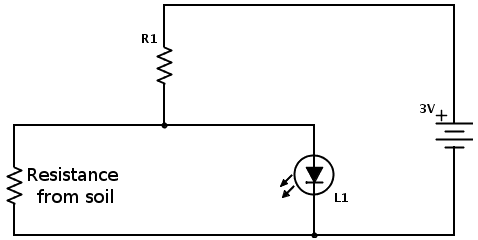
I was sitting at my desk at home, ready to start the project. Then I encountered my first problem. I did not have any resistors lying around at home. Luckily I found an old circuit board with resistors. So I desoldered the resistors from it and decided to try to make the circuit using those resistors.
But, after soldering a few of the parts I quickly realized that because of the high resistance in the soil when it is dry, I would need a large second resistor and thus would not get enough current to power the LED. I knew it couldn’t be that easy.

10 Simple Steps to Learn Electronics
Electronics is easy when you know what to focus on and what to ignore. Learn what "the basics" really is and how to learn it fast.
The Second Circuit Board Draft
So I figured I needed to add a transistor to the prototype circuit board and started drawing a new circuit:
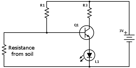
I found an old and used stripboard, put the components in place and started to solder. The smell of solder smoke filled the room.I used a BC546 transistor and powered it up. But still I could not get enough current to power the LED.”Hmm.. What to do?”, I thought to myself. “Well, add another transistor of course!”
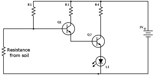
A Prototype Circuit Board That Works!
With another transistor in place I tried again. Still no luck. I did some calculations, then realized that I could increase the voltage a bit. Since I wanted it to be powered from AA batteries I could provide it with either 4.5 V (3 batteries) or 6 V (4 batteries). After some testing I found that I needed four batteries to make it work.Here is the final schematics:
Note that this is a prototype and not an optimized design. Things like battery consumption and calibration can be improved a lot.
Testing the Prototype
With a working prototype circuit board safely placed on my desk I decided to make the prototype more usable. So I cut it to make it easy to place in the soil of a plant.
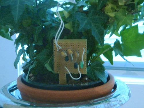
I brought the circuit over to Morten Hake’s house because I knew he had some dry plants. I tested it and it worked flawlessly!
What did I learn through this process?
- I got to refresh my electronics theory knowledge
- Having to desolder and reuse old circuit boards steals a lot of time, try to always have the necessary components and tools available when starting
Return from The Making of a Prototype Circuit Board to PCB Design
More Circuits & Projects Tutorials
Build Something Practical This Evening
Download this tutorial that shows you step by step how to build an old-school USB charger for your mobile.

Please explain the principals of measuring electrical current in soil. How does it work?
It’s actually as simple as measuring the resistance between two points in the soil.
Best,
Oyvind