
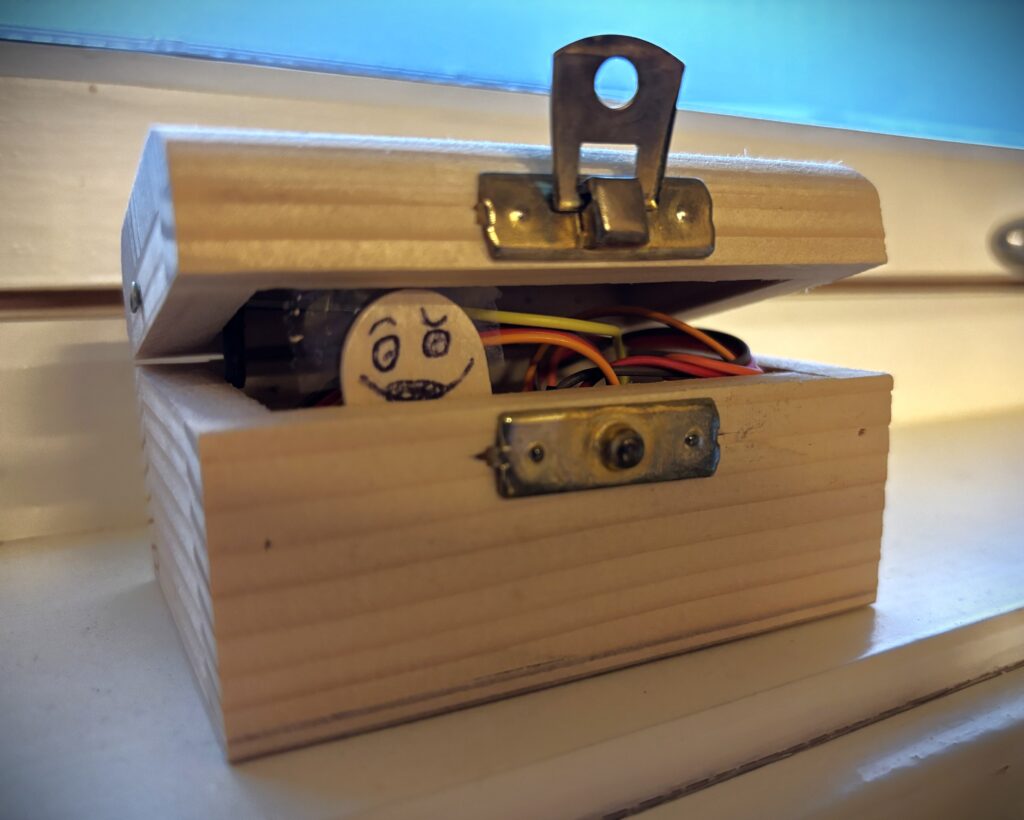
Knock on the box, and a grumpy little monster pops out to see who’s there.
I built this Halloween project for my daughter was she was only two and didn’t like scary things. So I wanted to build something cute and fun instead.
Here’s my mini monster box:
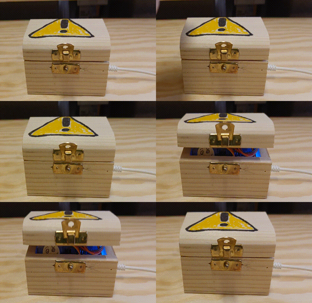
A microphone hears the knock, a one-transistor amplifier makes the signal big enough for an Arduino, and a servo opens the lid.
The lid opens at a random speed, stays open for a random time and closes at a random speed. Sometimes the monster peeks out carefully, and sometimes it pops up and slams the lid. That randomness is what makes it feel alive.
Here’s how to build it:
Mini Monster Box Schematic
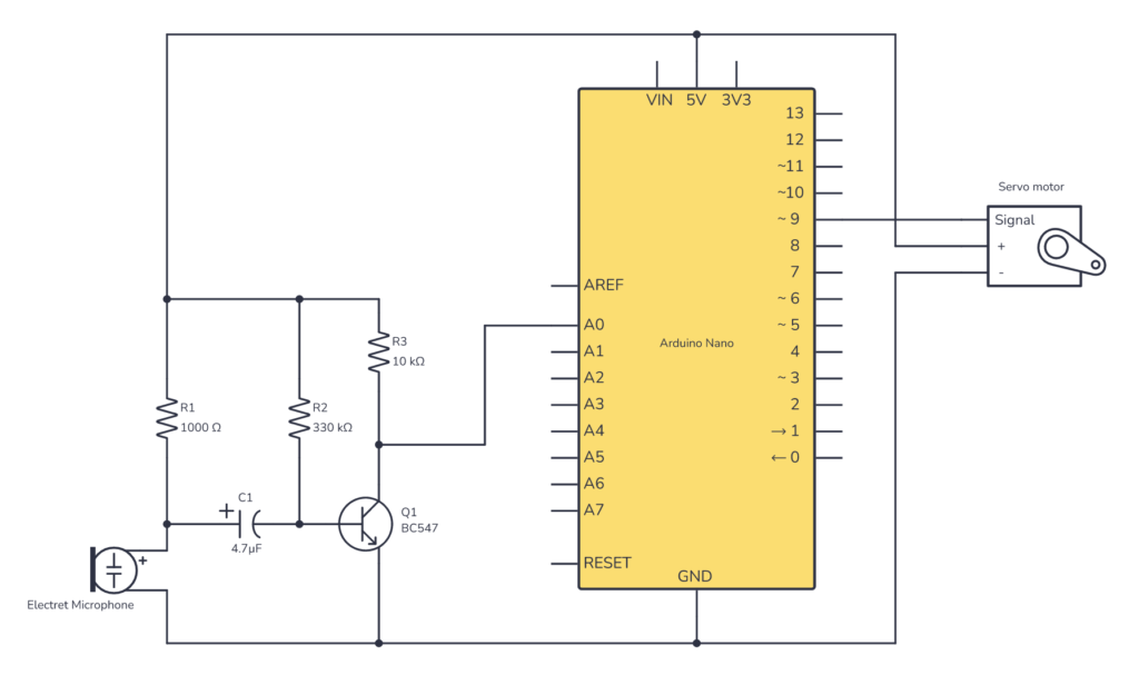
The circuit has four parts: microphone, amplifier, Arduino and servo.
Microphone An electret microphone needs a resistor up to plus to work. That’s R1’s job. When you knock, the microphone outputs a tiny voltage wiggle, just a few millivolts, on top of a steady DC voltage.
Build Something Useful This Evening
This gadget lets you use any IR remote-control to control your lamp, garden lights, heater oven, garage door, or anything else.
Amplifier That signal is far too small for the Arduino. It would get lost in the noise you always see on an analog input. So it goes through a simple transistor amplifier:
- C1 blocks the steady DC part and lets only the sound wiggle through.
- R2 sends a small current into the base of the transistor, so that it is turned on when there’s no signal coming in.
- R3 and the transistor work like a voltage divider, where the transistor is the bottom “resistor.” When a signal comes in, it affects the transistor’s “resistance” so that the voltage on the output changes.
When you knock, the tiny wiggle from the microphone pushes on the base of the transistor. And if the knock if loud enough, it will result in a few volts on the output of the amplifier.
Arduino The Arduino reads the amplified signal on A0 and keeps a running average of the readings. Random noise doesn’t move the average much, but a knock pushes it over the threshold. When that happens, it waits a moment and then runs the servo with a random opening speed, open time and closing speed.
Servo The servo moves the lid between closed (165°) and open (90°). To control the speed, the code moves it in small steps with a short pause between each one. Bigger steps make a faster lid.
How to calculate the values needed for detecting a knock
Step 1: Choose R3
R3 becomes the output impedance of your circuit. The datasheet for the microcontroller on the Arduino board (ATmega328P) recommends 10 kΩ or less for the analog inputs. So I chose 10 kΩ.
Step 2: Find the collector current (IC)
Normally for audio amplifiers, you’d want the collector current (IC) to be half of the maximum current, to have the most room for the output to swing. But in this case, where we just want to detect a loud noise, designing for maximum current is better. Then the output rests at around 0 V, and a noise pushes the voltage up.
With a 10 kΩ resistor, the maximum current is 5 V / 10 kΩ = 0.5 mA.
Step 3: Find the value of the bias resistor (R2)
The formula for the bias resistor is:
R2 = β · (VCC − 0.7 V) / IC
The 0.7 V is the voltage drop from the base to the emitter of the transistor. We have VCC of 5 V and IC of 0.5 mA. But the gain (β) is the tricky one. It can change a lot from one transistor to another, and even change with temperature.
Since we want the transistor fully on, a higher gain than expected isn’t a problem. It just turns the transistor on even harder. A lower gain is the problem. So use the lowest gain listed in the datasheet. For the BC547, that’s 110:
R2 = 110 × 4.3 V / 0.0005 A = 946 kΩ
946 kΩ is the largest value that keeps the transistor fully on. Use a smaller value to make sure it stays fully on, even with variations between transistors. The smaller the resistor, the louder the knock needed to trigger it. I used 330 kΩ, which works well for a firm knock. If your circuit needs a harder knock than you want, try a larger value like 470 kΩ or 680 kΩ.
Step 4: Choose the capacitor
The capacitor lets the sound signal from the microphone through while blocking the DC voltage. Together with the resistance around it, it forms a high-pass filter. Frequencies above the cutoff frequency pass, and lower frequencies get blocked:
f = 1 / (2π · R · C)
R is the mic’s resistor (1 kΩ) plus the resistance into the transistor’s base.
You can estimate the resistance into the base by dividing 26 mV (a constant for transistors at room temperature, called the thermal voltage) by the base current. With 330 kΩ as the bias resistor, the base current is 4.3 V / 330 kΩ ≈ 13 µA, so the resistance into the base is 26 mV / 13 µA ≈ 2 kΩ.
That gives a total R of about 3 kΩ.
A knock is mostly in the range from about 100 Hz up to a few kHz, so the cutoff just needs to be below that. Anything around 1 µF or more works. I used 4.7 µF, which gives a cutoff of about 11 Hz.
Building The Mini Monster Box
I built the circuit on a stripboard from Chip Quik. It has a mix of vertical and horizontal strips, and that turned out to be perfect for this circuit. I could connect the whole thing without cutting a single strip or using wires internally on the board.
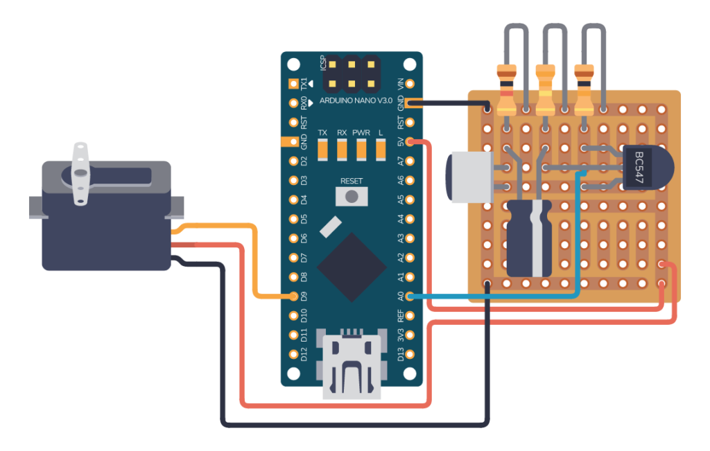
Then everything went into a box. I drew a tiny monster face, and I attached the servo motor to the lid so it can lift it open.
The Code
#include <Servo.h>

#define RUNNING_AVG_SIZE 10
#define CLOSED_POSITION 165
#define OPEN_POSITION 90

Servo myservo;
const int servoPin = 9;
const int soundPin = A0;
float averaged_value = 0;

int pos = 0;    // variable to store the servo position

void setup() {
  Serial.begin(9600);
  myservo.attach(servoPin);  // attaches the servo on pin 9 to the servo object
  closeLid(70);
}

void loop() {
  int sensorValue = analogRead(soundPin);

  // Averaging
  float alpha = 0.1; // factor to tune
  averaged_value = alpha * sensorValue + (1-alpha) * averaged_value;

  Serial.print("sensor = ");
  Serial.println(sensorValue);

  Serial.print("averaged_value = ");
  Serial.println(averaged_value);

  if (averaged_value > 500) {

    delay(1000);

    openLid(random(1, 5));
    delay(random(50, 2000));
    closeLid(random(1, 5));
    delay(2000);

    averaged_value = 0;
  }
}

void closeLid(int speed) {
  for (int pos = 90; pos < CLOSED_POSITION; pos += speed) { // goes from 0 degrees to 180 degrees
    // Make sure we don't go above CLOSED_POSITION:
    pos = min(pos, CLOSED_POSITION);
    myservo.write(pos);              // tell servo to go to position in variable 'pos'
    delay(15);                       // waits 15ms for the servo to reach the position
  }
}

void openLid(int speed) {
  for (int pos = 165; pos > OPEN_POSITION; pos -= speed) { // goes from 180 degrees to 0 degrees
    // Make sure we don't go below OPEN_POSITION:
    pos = max(pos, OPEN_POSITION);
    myservo.write(pos);              // tell servo to go to position in variable 'pos'
    delay(15);                       // waits 15ms for the servo to reach the position
  }
}
Make Your Own Version
This circuit is available with complete build instructions including parts list, schematic, and the stripboard layout over at Circuit Canvas: Mini Monster Box build instructions
From Circuit Canvas you can easily copy the circuit and make your own tweaks. Please do and let me know what you build in the comments below!
More Circuits & Projects Tutorials
Build Something Useful This Evening
This gadget lets you use any IR remote-control to control your lamp, garden lights, heater oven, garage door, or anything else.