Build The Knight Rider Light Bar Circuit With LEDs

The knight rider light bar circuit creates a running light similar to the light bar on the car from the television show Knight Rider.

It’s a really fun circuit to build. I once built a larger version of this for the inside of a party bus I was a part of. Unfortunately, I broke it the first day because I increased the voltage too much, but that’s another story.

You can build this circuit if you’re a total beginner, but of course, it’s a bit easier if you have already built a few circuits before.

Knight Rider Light Bar Circuit Diagram

To create the knight rider light bar, you need to build two parts; an oscillator and a counter.

Knight-Rider-Light-Bar-Circuit-Diagram

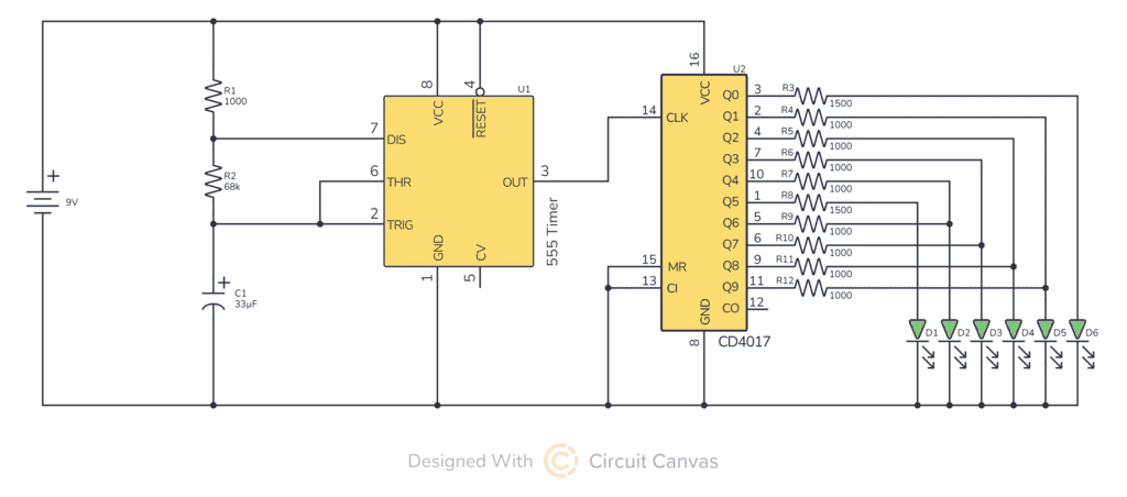
Note: The 4017 IC must be connected plus and minus through pins 16 (+) and 8 (-) for it to work.

Components Needed

  • A 555 Timer (Ex: NE555)
  • A 4017 Counter (Ex: CD4017BE)
  • R1: 1000 Ω
  • R2: 68 kΩ
  • R3 – R6: 100 Ω Use 1000 Ω instead
  • R8 – R11:100 Ω Use 1000 Ω instead
  • R7 and R12:220 Ω Use 1400 Ω instead
  • C1: 3.3 μF
  • D1 – D6: Standard LED

You can find these components at one of the many online electronics shops.

The Counter

The counter is built using the 4017 Decade Counter chip.

The counter sets one of its 10 outputs high depending on where in the counting sequence it is. So if it’s at 0, output 0 will be high. If it’s at 5, output 5 will be high. And if we have an LED connected to the output, the LED will light up.

There are only 6 LEDs, but 10 counter outputs. Each of the LEDs on the two sides connect to output 0 and output 9 as shown in the knight rider circuit diagram above.

The rest of the outputs each connect to two LEDs. This gives us a light that looks like it’s running back and forth.

The counter starts at 0 and increases every time it gets a pulse on its counter input.

The Oscillator

The oscillator is built around the 555 Timer chip.

This is the part that creates the pulses for the counter input. The speed of the oscillator (i.e. how many pulses it has per second) determines how fast the light will run back and forth.

The resistors R1, R2 and the capacitor C1 sets the frequency of the oscillator.

You can find the output frequency of your circuit by using the following formula:

Frequency = \frac{1.44}{(R1 + R2 + R2) * C1}

The frequency equals the number of pulses per second.

How To Build The Knight Rider Light Bar With LEDs?

The circuit can easily be built on a breadboard or on a prototyping board for soldering.

I usually like to build the circuit on a breadboard first. Just to make sure I understand it and am able to build it before soldering it onto a prototyping board.

Once the circuit is soldered, it’s a little bit harder to make changes if you messed something up. (But not too hard though, you can always desolder).

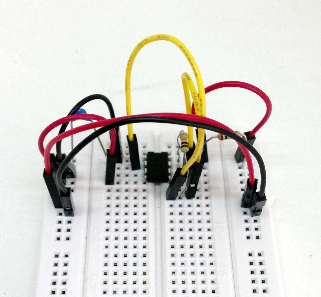
Step 1: Building the oscillator

Start by connecting the oscillator part. Connect it at the top of your breadboard so that you’ll have lots of space to connect the rest of the circuit below.

Then test the 555 timer oscillator by connecting an LED in series with a resistor on the output. With the values chosen above, your LED should blink about 3 times per second.

Make sure you get this to work before you move on to the next step. Also, make sure you remove the LED and the resistor before you continue.

555-timer-oscillator-breadboard

Step 2: Building the 4017 counter

Now that you know your oscillator is working, you can connect the remaining parts. Connect it as shown in the knight rider light bar circuit diagram shown above.
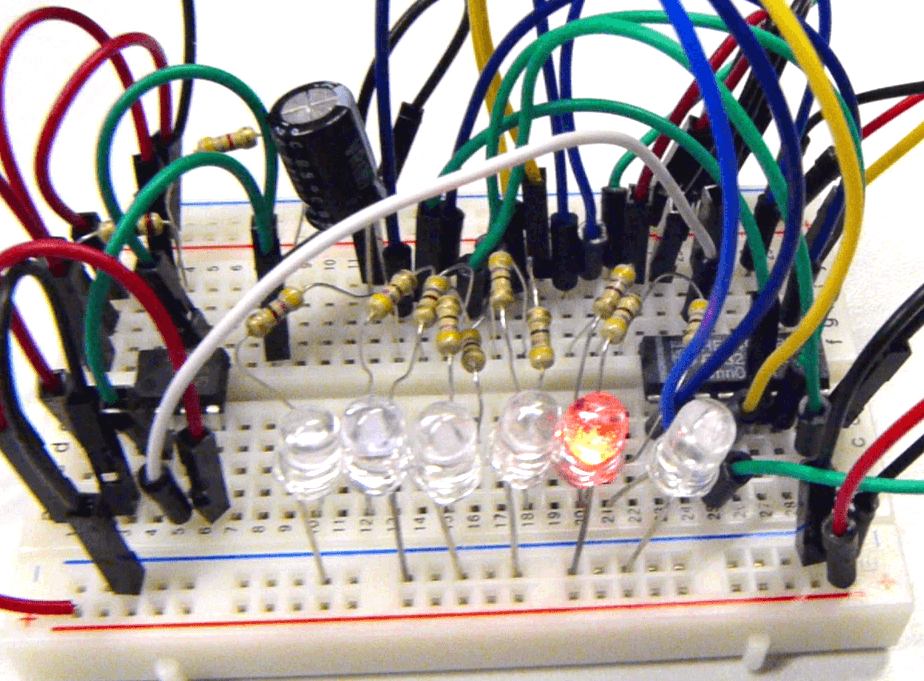
The knight rider light bar circuit on a breadboard

The Result

What If The Circuit Doesn’t Work?

If you followed my steps above, you know that your oscillator circuit is working. So something must be wrong with the counter circuit or in the connection from the oscillator to the counter. Start by checking that the connection between them is correct.

If no LEDs are lighting up, there’s a big chance that you’ve connected your LEDs in the wrong direction or that you are using the wrong value for the resistors. Check the direction of your LEDs and check that the resistors are 100 Ohm.

Only one LED should light up at a time. If more LEDs light up at the same time, you must have a faulty connection from the outputs of the counter to the LEDs. Inspect the ones that light up at the same time carefully to find the error.

Post your comment below if you tried to build this, and let me know how it went!

More Circuits & Projects Tutorials

29 thoughts on “Build The Knight Rider Light Bar Circuit With LEDs”

  1. Hi Oyvind,

    I see that you used voltage divider, am I right?

    Just want to ask when to use voltage divider and current divider. Could you please provide samples.

    Thanks

    Reply
    • Hey Japs,

      You’re right that R1 and R2 would make up a voltage divider yes. But in this case that’s more of a coincidence than a conscious design choice..

      Best,
      Oyvind

      Reply
  2. Hey, Oyvind! Curious minds want to know if it is possible to add more leds for a larger display. Don’t get me wrong, 6 is great but 10, 12, or even 20 leds would be spectacular

    Reply
  3. A shift register you say. Hmmmmm. I accept your challenge and will respond with my results. Thank you for your reply AND the idea.

    Reply
  4. Hello, your circuit is exactly what I was looking for to illuminate the “eye” of my next Cylon Raider model. Thank you so much for sharing it.
    My question is, does this same circuit work if I apply a 12-volt current, or do I have to change any component?
    Thanks in advance.

    Reply
  5. I don’t understand why you’ve used 100 Ohm resistors for LEDs D2-D5 and 220 Ohm ones for D1 and D6. Is it an aesthetic choice to make the end LEDs dimmer?

    Also, 100 Ohms seems a very low rating for a LED protection resistor, especially in a 9v circuit – most circuits I’ve seem use 330 or 470 Ohm resistors.

    Reply
    • The reason there are different values for D1 and D6 compared to the rest is because the rest have two paths for the current to take while D1 and D6 only one.

      Check for example D2. When output 4 is high, current flows from output 4 through D2 but also through R6 and back into output 6 which is low. So output 4 needs to supply more current than for example output 0.

      That said, I’m not sure exactly what calculations I used back in 2016 when posting this, because the current values are a bit high here.

      A quick mental calculation now gives me 1000 ohms for the resistor that are currently at 100 to get 5 mA for D2 to D5.

      And 1400 ohms for R7 and R12 should give you 5 mA for D1 and D6.

      Reply
      • I think a better design would be to feed the four tied outputs shown in the existing circuit into a CD4071 quad OR gate, and then send the outputs of those directly to each of these LEDs. Since the outputs on the 4017 aren’t tri-state, any time one of these LEDs is lit, about half the supplied current gets shunted into the resistor on the other output which is simultaneously pulled low.
        You’ve compensated for that by using lower-value resistors on the tied outputs, but this still limits the potential current in these LEDs significantly, since much of it gets shunted away. CD4000-series logic is limited to only about 5 mA current per output pin, which is barely enough to drive a small LED. With power-hungry LEDs, it would be impossible. Losing almost half the available current to a shunt resistor makes the problem much worse.
        With the change I suggest you could use the same resistor value for all 6 LEDs, providing uniform brightness and better power efficiency since ALL the supplied drive current would pass through the LEDs.
        In terms of parts, that would require an additional IC and save only four resistors, so it would be a slightly more costly circuit, but 4071s are pretty cheap!
        Even better, I’d recommend switching to using 74HC parts (74HC4017 counter + 74HC32 quad OR gate), since this logic family can drive up to 25mA per pin, allowing the circuit to be used with much larger/brighter LEDs. You’d need a 2-6V power source, though, rather than 9V.
        Either way, resistors must be sized appropriately based on the supply voltage, LEDs chosen, and the brightness level desired.

        Reply
  6. Hi,
    I was wondering why your description has changed to higher values of resistors? I made a 5V version with the original values 222 ohm and 100 ohm and it worked fine. Also I changed out the 68K for a 100K potentiometer allows the speed to be adapted.
    I was very pleased with this tutorial btw. Very cool its online since 2016 when tutorials ond these ICs were (i guess) a little harder to find. Today there aresome great ones on youtube that explain the function of all pins in detail.
    One thing though, why do you use output numbers instead of pin numbers? Do these change depending on the brand or version?
    In my 4017 the order of outputs in pins is 3,2,4,7,10,1,5,6,9,11. It took me some puzzling to relate output to pin numbers.

    All best. I m going to try your other circuits too!
    Jobbe

    Reply
    • If you look at the schematics, you can see that several of the outputs are connected to two LEDs instead of just one. If you connect just one LED to each output, it will go in just one direction, the restart from the beginning when it reaches the end.

      Reply

Leave a Comment